Installation
110
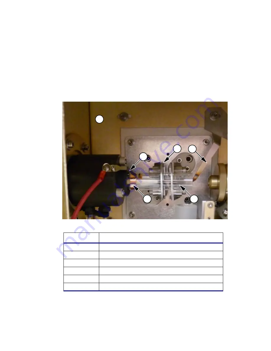
5. Make sure that the Ground Pointer is in close proximity to the end of the torch
glass but
not inside
the torch glass. If needed, push the Ground Pointer gently
slightly towards the rear of the torch box. Also make sure that the inner glass
tube in the torch is positioned 1.5 mm from the last turn of the plasma induction
plates.
Figure 4-7
Installing the torch into the sample compartment.
Item
Description
1
Front of Instrument Torch Compartment Door Open
2
Copper Foil Ignitor Contact (Part No. N0781097)
3
Plasma Induction Plates
4
Ground Pointer
5
Torch (Part No. N0780131)
6
Ignitor Contact Finger
1
5
6
2
4
3
Summary of Contents for OPTIMA 8000
Page 1: ...OPTIMA 8000 Customer Hardware and Service Guide ICP OPTICAL EMISSION Return to Document Menu...
Page 2: ......
Page 3: ...Optima 8000 Customer Hardware and Service Manual...
Page 12: ...Contents 10...
Page 18: ...16 Indicates the ON position of the main power switch Indicates alternating current...
Page 24: ...22 Figure C Location of warning labels in the sample compartment 1 2...
Page 28: ...26...
Page 29: ...Safety Practices 1...
Page 49: ...Preparing Your Laboratory 2...
Page 61: ...Preparing Your Laboratory 60...
Page 62: ...System Description 3...
Page 89: ...Installation 4...
Page 136: ...Maintenance 5...
Page 241: ...Troubleshooting 6...
Page 264: ...Error Messages 7...
Page 284: ......


