Installation
117
Fitting and Connecting the Autosampler Sampling Probe
Fitting the Sampling Probe
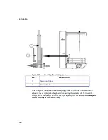
1. If not already done, carefully insert the sampling probe guide from above into
the sampling probe holder on the autosampler arm and push it down fully, as
shown in the following figure.
2. Carefully insert the sampling probe from above into the probe guide.
3. Push the sampling probe down until about 20 mm protrudes from the bottom end
of the probe guide, then position the O-ring on the probe to set this position, as
shown in the following figure.
This is not the final position for the sampling probe. The probe can be adjusted
when the rinsing port has been set up. See the following procedure,
Adjusting
the Sampling Probe Height
on page 119.
Caution
When you fit the sampling probe, take care
not
to press forcefully
in any direction on the autosampler arm since this can damage the
arm.
The sampling probe is a complete assembly. Do
not
attempt to
take the probe apart as this will damage it, and reassembly is not
possible.
Never
attempt to move the sampling probe holder along the
autosampler arm by hand. The autosampler may be damaged if the
tower is moved by hand when it is under system control.
Disconnect the power supply to the autosampler if you need to
manually move the tower
Summary of Contents for OPTIMA 8000
Page 1: ...OPTIMA 8000 Customer Hardware and Service Guide ICP OPTICAL EMISSION Return to Document Menu...
Page 2: ......
Page 3: ...Optima 8000 Customer Hardware and Service Manual...
Page 12: ...Contents 10...
Page 18: ...16 Indicates the ON position of the main power switch Indicates alternating current...
Page 24: ...22 Figure C Location of warning labels in the sample compartment 1 2...
Page 28: ...26...
Page 29: ...Safety Practices 1...
Page 49: ...Preparing Your Laboratory 2...
Page 61: ...Preparing Your Laboratory 60...
Page 62: ...System Description 3...
Page 89: ...Installation 4...
Page 136: ...Maintenance 5...
Page 241: ...Troubleshooting 6...
Page 264: ...Error Messages 7...
Page 284: ......


