Maintenance
211
Mira Mist Nebulizer
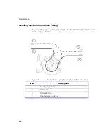
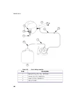
Sample Capillary Tubing
The capillary tubing is attached with UpChurch® 10/32 chromatographic fittings.
We supply 0.043 OD X 0.017 ID Poly Capillary tubing, but you may use any other
tubing that fits an UpChurch 10/32 fitting. We recommend that you use a 0.017" ID
or smaller ID capillary tube for the sample feed. This should catch any particles
before they get into the nebulizer. It is much safer & easier to replace the capillary
tubing than to clean the nebulizer.
The Mira Mist Nebulizer body is PEEK, the inner capillaries are Teflon. Generally
it will not break. If it is dropped such that the tip is deformed, then it will be
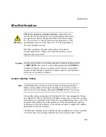
This device operates on compressed gases.
Appropriate care
must be taken. If in doubt about correct operating procedures, call
an experienced operator. Burgener Mira Mist Nebulizers require
45 - 55 psi to have a 1 liter per minute of Argon gas flow, so the
operating pressures are in the range of 25 - 45 psi, depending on
the torch optimum flow rate.
Mira Mist nebulizers will pulse if the pump can not deliver
constant sample flow: Change your pump tubing often, or use a
surgeless pump if possible.
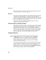
Caution
The gas orifice is at the very tip of the nebulizer. It is made of Teflon which
is
VERY SOFT
. This tip is very easily damaged and should
NEVER
be
touched with fingers, tissues, or anything else. If the tip is accidentally
touched, and the nebulizer continues to operate, then it is still functional,
and its use can be safely continued.
Note
The PEEK Mira Mist body has 10/32 threads for the gas and capillary
fittings. Gently tighten until snug for the sample line. For the gas line, if
there seems to be any leakage, then tighten
HARD
. PEEK is very strong.
!
Warning
Summary of Contents for OPTIMA 8000
Page 1: ...OPTIMA 8000 Customer Hardware and Service Guide ICP OPTICAL EMISSION Return to Document Menu...
Page 2: ......
Page 3: ...Optima 8000 Customer Hardware and Service Manual...
Page 12: ...Contents 10...
Page 18: ...16 Indicates the ON position of the main power switch Indicates alternating current...
Page 24: ...22 Figure C Location of warning labels in the sample compartment 1 2...
Page 28: ...26...
Page 29: ...Safety Practices 1...
Page 49: ...Preparing Your Laboratory 2...
Page 61: ...Preparing Your Laboratory 60...
Page 62: ...System Description 3...
Page 89: ...Installation 4...
Page 136: ...Maintenance 5...
Page 241: ...Troubleshooting 6...
Page 264: ...Error Messages 7...
Page 284: ......


