System Description
70
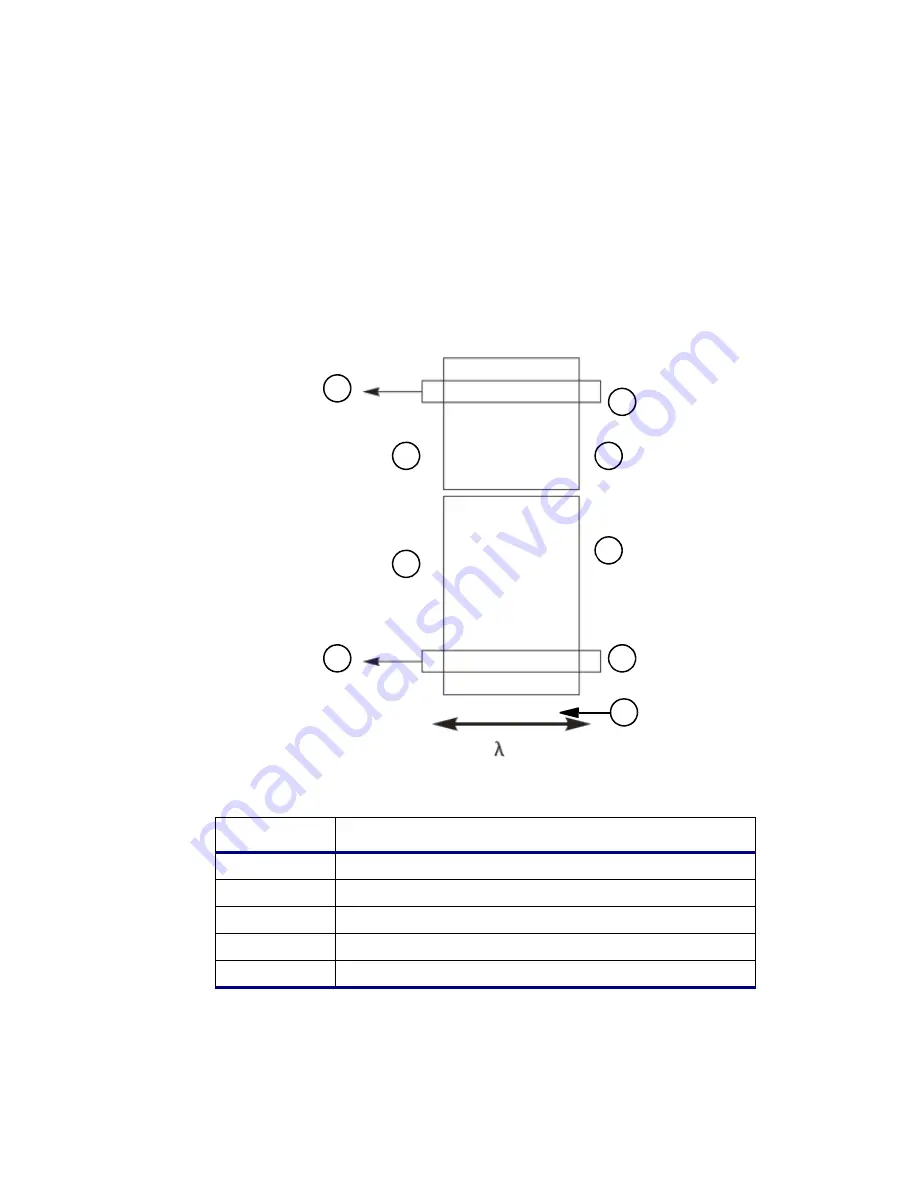
The rear of the actual detector area is thinned to a few micrometers to allow
illumination from the rear. This prevents the absorption of radiation by components
other than the detector pixels and maximizes the quantum efficiency without the use
of a fluorescent coating.
Figure 3-4
Detector
Item
Description
1
Output
2
Register for the reference measurement.
3
2 mm
4
CCD Array
5
3.5 mm
1
3
5
7
2
4
6
8
9
Summary of Contents for OPTIMA 8000
Page 1: ...OPTIMA 8000 Customer Hardware and Service Guide ICP OPTICAL EMISSION Return to Document Menu...
Page 2: ......
Page 3: ...Optima 8000 Customer Hardware and Service Manual...
Page 12: ...Contents 10...
Page 18: ...16 Indicates the ON position of the main power switch Indicates alternating current...
Page 24: ...22 Figure C Location of warning labels in the sample compartment 1 2...
Page 28: ...26...
Page 29: ...Safety Practices 1...
Page 49: ...Preparing Your Laboratory 2...
Page 61: ...Preparing Your Laboratory 60...
Page 62: ...System Description 3...
Page 89: ...Installation 4...
Page 136: ...Maintenance 5...
Page 241: ...Troubleshooting 6...
Page 264: ...Error Messages 7...
Page 284: ......


