System Description
83
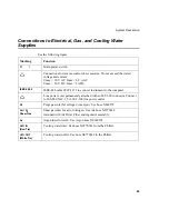
Connections to Electrical, Gas, and Cooling Water
Supplies
See the following figure.
Marking
Function
O I
Main power switch.
Connections for remote control of accessories. Do not exceed the stated
voltage and current:
Umax = 30 V AC, Imax = 0.5 A AC
Umax = 30 V DC, Imax= 2 A DC
IEEE 488.2
IEEE-488 cable 0999-1355 to connect instrument to the computer.
Line power cord, permanently attached with an IEC 309 connector. Connect
to 200-240 VAC, 15 A, IEC-309 line power outlet.
N
2
Purge gas inlet for nitrogen (or argon). Use hose N069275
Air / N
2
Shear Gas
Shear gas inlet for air or nitrogen. Use Air hose N0770348
included with Air Dryer Filter and regulator assembly.
Ar
Argon inlet for torch. Use Argon hose N0690274.
H
2
O IN
(Red Tie)
Cooling water inlet. Use hose N0770341 from the Chiller.
H
2
O OUT
(White Tie)
Cooling water outlet. Use hose N0770342 to the Chiller.
Summary of Contents for OPTIMA 8000
Page 1: ...OPTIMA 8000 Customer Hardware and Service Guide ICP OPTICAL EMISSION Return to Document Menu...
Page 2: ......
Page 3: ...Optima 8000 Customer Hardware and Service Manual...
Page 12: ...Contents 10...
Page 18: ...16 Indicates the ON position of the main power switch Indicates alternating current...
Page 24: ...22 Figure C Location of warning labels in the sample compartment 1 2...
Page 28: ...26...
Page 29: ...Safety Practices 1...
Page 49: ...Preparing Your Laboratory 2...
Page 61: ...Preparing Your Laboratory 60...
Page 62: ...System Description 3...
Page 89: ...Installation 4...
Page 136: ...Maintenance 5...
Page 241: ...Troubleshooting 6...
Page 264: ...Error Messages 7...
Page 284: ......


