background image

94 .


RamanMicro 300 Getting Started Guide 


Replacing the Stage Controller Fuse 

NOTE: This section is only applicable if you have a motorized microscope stage. 


WARNING 

Electrical hazard 

To prevent potential injury to yourself and damage to the instrument, 

switch OFF all components in the system and disconnect them from the 

line power supply before you alter, or make any new, electrical 

connections. 

Removal of the protective housing or exterior panels on any instrument 

will allow potentially hazardous Class 3B laser radiation to be emitted 

and will invalidate the instrument warranty. 

1.


Switch off the stage controller, disconnect it from the power supply and remove the 

mains cord. 

2.


Insert a screwdriver into the slot at the side of the fuse drawer, and pull out and flip to 

one side over the mains inlet. 
The fuse may now be removed. 

3.


Fit the replacement fuse into the fuse drawer. 
Make sure that you fit the fuse in the top slot. You require a 1.6 A time-lag fuse 

(09991641). Always use the recommended replacement fuse. 

4.


Refit the fuse drawer. 

The only other fuses that you may have to replace are those in the plugs of the mains power 

cords for the spectrometer and microscope (UK-type plugs only).  


Summary of Contents for RamanMicro 300 Series

Page 1: ...RamanMicro 300 Series Getting Started Guide MOLECULAR SPECTROSCOPY...

Page 2: ...t limited to the implied warranties of merchantability and fitness for a particular purpose PerkinElmer shall not be liable for errors contained herein for incidental consequential damages in connecti...

Page 3: ...9 Specifications 30 PC Requirements 31 Hardware Requirements 31 Software Requirements 32 Windows Administrator Level 32 Finding a Suitable Location for the RamanMicro 300 33 Instrument Dimensions 34 I...

Page 4: ...Verification 81 SOP 9 Wavelength Calibration Verification of the RamanMicro 300 83 SOP 10 Wavelength Calibration of the RamanMicro 300 84 SOP 11 Laser Frequency Calibration of the RamanMicro 300 85 SO...

Page 5: ...Introduction...

Page 6: ...and warnings used in the manual Safety Practices This chapter outlines the electrical and laser safety issues We recommend that all users read this chapter Raman History Theory and Instrumentation Th...

Page 7: ...to show that you have to press two keys at the same time for example ALT F All eight digit numbers are PerkinElmer part numbers unless stated otherwise The term instrument means the RamanMicro 300 Ra...

Page 8: ...n otros En recuadros ste se proporciona informaci n sobre este tipo de circunstancias Caution Attention Nous utilisons le terme CAUTION ATTENTION pour signaler les situations susceptibles de provoquer...

Page 9: ...os recuadros como ste se proporciona informaci n sobre este tipo de circunstancias Warning Danger Nous utilisons la formule WARNING DANGER pour avertir des situations pouvant occasionner des dommages...

Page 10: ...10 RamanMicro 300 Getting Started Guide...

Page 11: ...Safety Practices...

Page 12: ...to be correct and complete PerkinElmer shall not be liable for errors contained herein nor damages concerned with the use of this document PerkinElmer does not accept liability for the interpretation...

Page 13: ...following conditions Temperature 15 C to 30 C Relative Humidity 75 maximum non condensing Avoid any adjustment maintenance or repair of the opened operating instrument If any adjustment maintenance o...

Page 14: ...use Altitude up to 2000 m Ambient temperatures of 5 C to 40 C Mains fluctuations not exceeding 10 of the nominal voltage WARNING If the equipment is used in a manner not specified herein the protectio...

Page 15: ...country listed as the shipping destination WARNING If the power cord is not appropriate for your country it must be removed from use immediately and replaced If the power cord has any physical damage...

Page 16: ...nst any unauthorized operation and contact PerkinElmer for advice before using the instrument again The RamanMicro 300 emits a focused beam of laser radiation at 785 nm from the microscope objective l...

Page 17: ...visible radiation up to a maximum of 0 5 W continuous wave CW is longer than 0 25 s They present a hazard to the eye if the direct beam or spectral reflections are viewed without appropriate protectio...

Page 18: ...y officer or laboratory manager should control the use of this key Laser Warning Labels Laser warning labels are attached to the instrument for your safety Please observe the necessary precautions For...

Page 19: ...le from PerkinElmer part number L1323518 Use an interlock switch on the door to the laboratory if required WARNING Do not make any adjustments to the microscope or any part of the system when experime...

Page 20: ...the manual to find out the nature of the potential hazard and any actions which have to be taken Labels on the Exterior of the Microscope Figure 2 Labels on the microscope LASER APERTURE CAUTION CLASS...

Page 21: ...Raman History Theory and Instrumentation...

Page 22: ...erved the scattering from water and alcohol visually In addition to the blue incident light a faint green light also scattered later named Stokes scattering By the 1930s much of the theory underlying...

Page 23: ...Stokes scattering or shorter wavelengths higher frequencies Anti Stokes scattering With Stokes scattering some of the incident photons give up a portion of energy to the molecules and are detected at...

Page 24: ...ional energy of the molecule The frequency shifts from the frequency of the incident beam are displayed on the x axis of a Raman spectrum generally in relative wavenumbers otherwise known as Raman Shi...

Page 25: ...ange of sample types that you can analyze Figure 6 The RamanMicro 300 microscope The microscope Figure 6 is composed of a frame illumination module Raman module and alignment camera module This is con...

Page 26: ...anMicro 300 Getting Started Guide Figure 7 Schematic of the RamanMicro 300 connected to the RamanStation 400F or RamanFlex 400 Laser CCD detector Spectrograph Optical head RamanMicro 300 Spectrometer...

Page 27: ...e light is further dispersed vertically onto the CCD detector The light is spread over a number of strips on the CCD that are read simultaneously therefore a full spectral range at high resolution can...

Page 28: ...e absence of moving parts also means that as you acquire the spectrum there is no change in the spectrograph s stray light performance meaning that there are no stitch marks in the final spectrum No l...

Page 29: ...Preparing Your Facility...

Page 30: ...F 30 C 86 F Recommended Temperature 20 C 68 F 25 C 77 F Power Supply 100 240 V 10 50 60 Hz Primary Fuse See Olympus manual 1 6 A T time lag If the electricity supply does not conform to these specific...

Page 31: ...ware must meet the following minimum specifications Intel Pentium 4 400 or 533 MHz processor At least 256 MB of Random Access Memory RAM Video card and monitor capable of displaying at least high colo...

Page 32: ...wnloads Windows Administrator Level It is important to note that you must be logged on at Administrator level on Windows before installing the software Logging on as an Administrator ensures that inst...

Page 33: ...ower points 1 for the microscope 1 for the stage control box in addition to the power points required for the spectrometer module The workbench must be flat and level The workbench where the microscop...

Page 34: ...o 300 microscope module weighs approximately 20 kg Laboratory benching must be strong enough to support the combined weight of the microscope spectrometer and any ancillary equipment without warping o...

Page 35: ...Installing Your RamanMicro 300...

Page 36: ...cription L1320243 Olympus BX51 Microscope L1320261 Raman Module L1320245 Alignment Camera Assembly for Microscope LX108870 OR LX108871 Spectrum Std for Raman Software Kit Contains the Spectrum Std Sof...

Page 37: ...21689 Z axis Adapter Cable systems with motorized stages only LX108897 SpectrumIMAGE Software Kit systems with motorized stages only NOTE You instrument is intended for installation by a PerkinElmer S...

Page 38: ...e RamanMicro 300 microscope module weighs 20 kg To avoid injury or damage to the instrument please use proper lifting techniques WARNING To lift and or move the instrument safely requires two people W...

Page 39: ...ibed in this section Fitting the Stage on the Microscope To fit the stage 1 Unpack the stage from the shipping material 2 Remove the objective nosepiece from the microscope 3 Carefully locate the stag...

Page 40: ...the socket labeled JOYSTICK on the rear panel of the stage controller box Figure 13 Figure 13 Rear panel of the Stage Controller Box 2 Connect the cable from the socket on the right side of the stage...

Page 41: ...ormation 1 Slide the focus motor sleeve over the z axis drive control on the left side of the microscope and then tighten the connections using an allen key OR Push the focus motor into the sleeve unt...

Page 42: ...ination source in position against the rear of the illuminator module 2 Using the allen key supplied Figure 15 fasten the two screws so that the source is supported 3 Connect the black cable from the...

Page 43: ...re 16 Connecting the Raman module Connecting the Alignment Camera to the Raman Module The alignment camera module is then connected into the mounting bracket on top of the Raman module and the screws...

Page 44: ...des two sets of connectors For a RamanFlex 400F either set can be used for a RamanFlex 400 only the left hand set should be used to connect a RamanMicro 300 1 Connect the excitation cable L1323331 fro...

Page 45: ...fiber with the white cable marker is attached to the Raman module Make sure that the polarizing ridge on the FOP cable is aligned with the slot in the coupler casing before carefully pushing the cabl...

Page 46: ...new version of Spectrum Software on page 99 of Troubleshooting NOTE Before connecting the PC to the spectrometer module you must install the Spectrum software Before installation please ensure that A...

Page 47: ...is required If you are upgrading an existing system with a RamanMicro 300 you will require the assistance of a PerkinElmer Service Engineer to upgrade various configuration files The Installation Wiza...

Page 48: ...Requirements starting on page 31 an appropriate error message will inform you of the problem You will need to correct this problem before the installation can be performed 4 Click Next The License Agr...

Page 49: ...enter an incorrect license number the Next button is disabled The Spectrum Beer s Law check box is automatically selected when you select the Spectrum check box You do not need to enter a license num...

Page 50: ...ted page is displayed 9 Click Finish Before you can collect spectra you must configure your Raman instrument 10 Place your Raman Instrument Installation Disk LX108925 into your CD drive 11 If the inst...

Page 51: ...s while the system is preparing to install the software When the installer is ready the Welcome to the InstallShield Wizard for Raman Instrument page is displayed 13 Click Next The License Agreement p...

Page 52: ...Micro 300 Getting Started Guide 15 Click Install to begin installing the Raman instrument The Installing Raman Instrument page is briefly displayed During this installation the DirectX Setup page is d...

Page 53: ...s you of the status of the installation 17 Click Next The Raman Instrument Install Wizard opens at the Welcome page NOTE Ensure that the USB cable from your alignment camera on the RamanStation and or...

Page 54: ...displayed on the rear panel of the instrument 21 Click Add Raman Instrument If you have already installed PerkinElmer software on the PC the PerkinElmer Login dialog is displayed Login as a PerkinElm...

Page 55: ...vigate to their location before you click Copy Configuration Files The Install PerkinElmer Raman Instrument page is displayed 23 Attach your RamanStation to the PC using the supplied USB 2 0 cable L13...

Page 56: ...w Hardware Wizard page is displayed NOTE The Found New Hardware Wizard page may inform you that it is helping you install software for USB Device In this case continue with the installation in the sam...

Page 57: ...navigate to C Program Files PerkinElmer ServiceIR Raman 28 Click Next The Completing the Found New Hardware Wizard is displayed 29 Click Finish The Found New Hardware Wizard closes 30 On the Install P...

Page 58: ...d Completed page is displayed 32 Click Finish The Raman Instrument Installer Information dialog is displayed 33 Click No 34 Plug the USB cable from your alignment camera into the USB socket in the sam...

Page 59: ...OR If not go to Step 45 37 Navigate to C Program Files PerkinElmer ServiceIR Raman Videology and double click on Autorun exe The Welcome to Videology USB2 0 Camera Installation Wizard page is display...

Page 60: ...icro 300 Getting Started Guide 40 Click Finish The Videology USB2 0 Camera Software Setup page is displayed 41 Click Install Viewer The Welcome to the InstallShield Wizard for Videology USB Viewer is...

Page 61: ...icro 300 61 42 Click Next The Choose Destination Location page is displayed 43 If required click Change and navigate to your chosen destination folder and then click Next The Ready to Install the Prog...

Page 62: ...e InstallShield Wizard Complete page is displayed 45 Click Finish 46 Restart your PC This completes the installation of the Spectrum software NOTE You should not allow the PC to enter Standby mode On...

Page 63: ...it up to 4 objectives 1 Select the highest magnification objective lens on the microscope either the 100x or 50x 2 Select the Bright Field BF switch position on the Olympus illuminator module 3 Place...

Page 64: ...very far from the crosshair a complete realignment of the video camera is required 1 Select the 50x objective lens on the microscope 2 Select the Dark Field DF switch position on the Olympus illuminat...

Page 65: ...era menu 14 If required select Save Calibration from the Calibrate menu to save the new settings Aligning the Raman Coupler You should only adjust the Raman coupler if the signal throughput has decrea...

Page 66: ...ning the Laser Path The laser path only needs realignment if the beam is observed to move grossly in the xy plane when moving into and out of focus If the laser path is aligned correctly then the lase...

Page 67: ...t Please contact PerkinElmer for advice about removing the fiber optic cables that connect the spectrometer and microscope modules If you need to ship your instrument you must use the original supplie...

Page 68: ...68 RamanMicro 300 Getting Started Guide...

Page 69: ...Using the RamanMicro 300...

Page 70: ...spectrometer see Calibration and Performance Verification SOPs on page 81 SOP 1 Turning the Raman System On The RamanMicro 300 must be used in conjunction with the RamanStation 400F or RamanFlex 400...

Page 71: ...ff NOTE We recommend that you leave the spectrometer module switched on when possible 1 Shut down Spectrum software by selecting Exit from the File menu to return to the Windows operating environment...

Page 72: ...n using long working distance objectives for example Long Working Distance Objective Lens Kit L1323347 the working distance depends on the objective usually 2 10 mm Set the highest position of the sta...

Page 73: ...tor module 6 Switch on the illumination source The switch is located on the right side of the microscope frame 7 Set the required light intensity using the adjustment knob on the right side of the mic...

Page 74: ...ber there is no best objective High magnification objective lenses give the most efficient Raman collection from thin samples like films or wafers but low magnification objectives are better for macro...

Page 75: ...th drop down list 9 Click to open the Alignment Camera window 10 Use the joystick to move the stage or click Stage Control and then use the appropriate fields in the Sample Position section to focus o...

Page 76: ...tral data from that location It can also be used to enhance the signal to noise ratio of spectral data The data displayed on screen during a spectral preview cannot be saved To save data you must coll...

Page 77: ...ns Typical values for Scan time and Number of scans are 5 seconds and 5 scans respectively Spectra may be optimized by increasing or decreasing the Scan time and Number of scans To obtain a good signa...

Page 78: ...ers are stored as the default parameters in the software NOTE The Spectrum software automatically saves to the currently loaded REX file without prompting any configuration changes made that affect th...

Page 79: ...of scans and a minimum of 1 Background Handling Renew background at start of each sample Experiment page Advanced tab Yes Sampling Area Experiment page Sampling tab Select the number and style of samp...

Page 80: ...older in which the scan data will be stored NOTE If you choose to save spectra to a folder other than the default one specified for your instrument the data will not be displayed automatically To view...

Page 81: ...instrument or accessory or if there have been appreciable temperature variations in the local environment Backgrounds are always collected during a calibration procedure The background measures the bi...

Page 82: ...that the instrument has been brought back within specification If the wavelength calibration verification fails because the spectral intensity is low then this may also be due to the calibration samp...

Page 83: ...Cover the microscope with dark cloth to minimize stray light from interfering with the calibration and ensure that caps are placed on any external fiber optic probes or accessories 10 Select Validate...

Page 84: ...e 28 Attaching the calibration accessory NOTE As wavelength calibration is not required on a regular basis the external neon calibration accessory is not included in the basic RamanMicro 300 package T...

Page 85: ...wer is set to 100 6 Click Spectral Preview in the Scan and Instrument Setup dialog and focus on a sample of polystyrene L1181228 When the polystyrene sample is optimally focused close the Scan and Ins...

Page 86: ...ent Setup dialog and on the Hardware tab select Microscope 50x from the Beam path drop down list 5 Ensure that the laser power is set to 100 6 Click Spectral Preview and then focus on the NIST standar...

Page 87: ...as well as the microscope objective lenses Ensure that the fiber optic probe has a lens cap in place during intensity calibration of the objectives Summary The only calibration procedure that needs to...

Page 88: ...bjective lenses Sampling Accessories Part Number Description L1323514 Quartz microscope slide 25 75 1 mm L1860335 Tablet holder kit for motorized stage L1860336 Powder holder kit for motorized stage L...

Page 89: ...ins external interlock cable laser safety goggles laser detection card and door warning label L1320266 RamanMicro calibration kit L1321843 sCAL Raman calibration standard L1323503 Replacement laser ke...

Page 90: ...90 RamanMicro 300 Getting Started Guide...
Page 91: ...Maintenance and Troubleshooting...

Page 92: ...u clean the entire instrument Avoid spilling liquid into the instrument or accessories Clean all external spills immediately If anything that is spilled enters the main body of the spectrometer make t...

Page 93: ...questions regarding maintenance or servicing The optical surface of all microscope objectives should be left free from debris To clean the lenses wipe clean with alcohol soaked cotton swabs or lint fr...

Page 94: ...us Class 3B laser radiation to be emitted and will invalidate the instrument warranty 1 Switch off the stage controller disconnect it from the power supply and remove the mains cord 2 Insert a screwdr...

Page 95: ...SB 2 0 power hub Problem The software installation stops during the Philips VCheck step Description In the VCheck dialog that is displayed while the software performs a number of checks on your system...

Page 96: ...w Hardware Wizard page is displayed NOTE The Found New Hardware Wizard page may inform you that it is helping you install software for USB Device In this case continue with the installation in the sam...

Page 97: ...ed 9 Click Finish The Found New Hardware Wizard closes Problem A motorized sample accessory does not go to the correct position when asked Description This means that for some reason the motorized sta...

Page 98: ...nterlocked doors are closed properly Solution 2 Ensure your external interlock is wired up correctly and that any interlocked room entrances or sampling enclosures are closed Software Problem Scan and...

Page 99: ...the front Raman Flex 400 Series or rear RamanStation 400 Series panel of the spectrometer is set to the ARM position Problem Detector cannot achieve operational temperature Description During system...

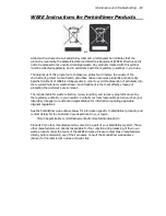
Page 100: ...contamination The customer s responsible body is required to follow the Equipment Decontamination Procedure and complete the Certificate of Decontamination These documents are available on the PerkinE...

Page 101: ...most effective means of protecting the customer s environment The requirements for waste collection reuse recycling and recovery programs are set by the regulatory authority in your location Contact...

Page 102: ...102 RamanMicro 300 Getting Started Guide...

Reviews: