Air Inlet and Exhaust
System
i06512664
Valve
Lash
-
Adjust
Table
1
Required Tools
Tool
Part Number
Part Name
Qty
A
SE253
Crankshaft Turning Tool
1
B
-
Feeler gauge
1
NOTICE
Only qualified service personel should perform this
maintenance. Refer to the Service Manual or your au-
thorized Perkins dealer or your Perkins distributor for
the complete valve lash adjustment procedure.
Operation of Perkins engines with incorrect valve
lash can reduce engine efficiency, and also reduce
engine component life.
Ensure that the engine cannot be started while
this maintenance is being performed. To help pre-
vent possible injury, do not use the starting motor
to turn the flywheel.
Hot engine components can cause burns. Allow
additional time for the engine to cool before
measuring/adjusting valve lash clearance.
Note: The valve bridges must be set before the
valve lash is adjusted.
Illustration 5
g01359594
Eight cylinder engine
(A) Inlet valve
(B) Exhaust valve
Ensure that all power is disconnected to the engine.
Illustration 6
g01241573
Typical example
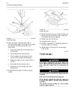
1.
Remove the capscrews (1).
2.
Remove the rocker cover (2).
3.
Remove the joint (not shown).
4.
Repeat steps 1 through 3 for the remaining rocker
covers.
For 4008-30 engine, set the valve lash in the
sequence that is shown in the table 2 .
Table 2
Eight cylinder engine
Top Center Position
Engine cylinder with valves on the rock
Set the bridge adjustment and set valve
lash.
1-8
8
1
4-5
5
4
(continued)
18
M0064276


