Chapter 5
TPD 1399E
Page 16
Keel cooling system
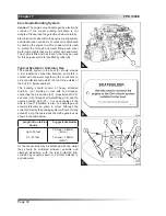
The M65 and M85T may be purchased in a form
suitable for keel cooling. The engine connections
provided for the cooler are to suit 32mm outside
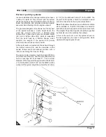
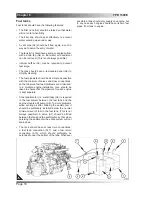
diameter rigid pipe, as shown in (A) and (B). The
connection for the flow to the keel cooler is shown at
(B1) and the return at (A1). The design data for the
keel cooler is shown in the table below.
M65
M85T
Heat rejection
at rated power
40 kW (2300
Btu/min)
51kW (2908
Btu/min)
Design value for
the temperature
of the water
returning from
the keel cooler.
60
O
C
60
O
C
Design value
for the water
flow through the
keel cooler.
90 litres/min (20
imp galls/min)
90 litres/min (20
imp galls/min)
The pipework between the engine and the cooler
should be as short and direct as is possible, but
should be sufficiently flexible to allow the engine to
move on its anti-vibration mounts.
The pipe layout should discourage the formation of air
locks, and venting points should be provided wherever
an air lock is likely to occur.
The keel cooling system should normally be filled
with a water/anti freeze mixture containing 50%
antifreeze, to ensure that the inhibitors included in the
antifreeze are present at a sufficient level to minimise
corrosion.
Note:
The illustrations show the connections on the
M65, but are the same on the M85T.
Summary of Contents for M65
Page 1: ... Installation Manual GB Part No TPD 1399E M65 M85T ...
Page 2: ......
Page 4: ...TPD1399E ...
Page 20: ...Chapter 4 TPD 1399E Page 14 ...
Page 26: ...Chapter 6 TPD 1399E Page 20 ...
Page 28: ...Chapter 7 TPD 1399E Page 22 ...
Page 33: ...TPD 1399E Chapter 7 Page 27 ...
Page 34: ...Chapter 7 TPD 1399E Page 28 ...
Page 38: ...Chapter 7 TPD 1399E Page 32 ...
Page 40: ...Chapter 8 TPD 1399E Page 34 ...
Page 44: ...Chapter 9 TPD 1399E Page 38 ...
Page 46: ...Chapter 10 TPD 1399E Page 38 ...
Page 52: ...Chapter 11 TPD 1399E Page 44 ...


