background image

S

amu

el


H

ea

th

DO

OR

PAT

EN

TS

AP

PL

IE

FO

R

PER

KO

POW

ERM

ATIC

C

LO

SI

N

G

SP

EE

D

+


E

S

amu

el


H

ea

th

DO

OR

PAT

ENT

S

APP

LIE

D F

OR

CLO

SIN

G

SPE

ED

+    

 –

C

E

D

D

PERK

O

POW

ERM

ATI

C

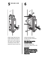
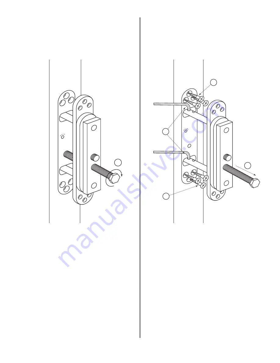
• Insert closer body into door.

• Insert extractor bolt (E) into

position and rotate clockwise

until holes in link rods appear. 

• Generally for thicker doors

expose both holes on each rod.

INSTALLING CLOSER

5

• Insert the allen keys (C)

through both top and bottom

link rod holes.

B

Bo

otth

h a

alllle

en

n k

ke

ey

yss m

mu

usstt b

be

e

cco

orrrre

eccttlly

y llo

occa

atte

ed

d..

• Remove extractor bolt.

• Secure door plate to door with

six screws (D).

IIM

MP

PO

OR

RT

TA

AN

NT

T

W

Wiitth

h cco

om

mp

po

ossiitte

e d

do

oo

orrss a

an

nd

d d

do

oo

orr

lliin

niin

ng

gss iitt iiss e

esssse

en

nttiia

all tto

o d

drriillll p

piillo

ott

h

ho

olle

ess Ø

Ø 

3

3

//

3

32

2

” ((2

2..5

5m

mm

m))  tto

o ssu

uiitt

ffiix

xiin

ng

g ssccrre

ew

wss..

6

Summary of Contents for POWERMATIC R100

Page 1: ...conform to power size 3 of Controlled Door Closing Device BS EN1154 1997 Test door 60kg 132lbs UL Approved to UL 10B UL 10C and UL 228 ADA Compliant ANSI 156 4 Reg 1 Hour Fire Test BS EN1634 1 2000 Ad...

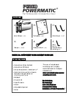
Page 2: ...al ll la at ti io on n o of f P Pe er rk ko o P Po ow we er rm ma at ti ic c power latching action closing speed Samuel Heath patents applied for UL C US PARTS LIST C CH HE EC CK K A AL LL L C CO OM...

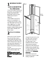
Page 3: ...12 of a hinge ensuring the center line is central in line with the pivot point of the hinge Draw a vertical line at the center point of the door edge on the template N NB B T Th hi is s l li in ne e m...

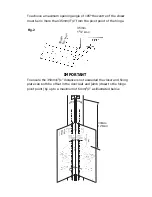
Page 4: ...plate can both be offset in the door leaf and jamb closer to the hinge pivot point by up to a maximum of 6mm 1 4 as illustrated below To achieve a maximum opening angle of 105 the centre of the closer...

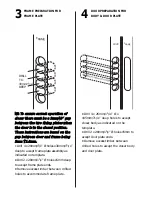
Page 5: ...b be et tw we ee en n d do oo or r a an nd d f fr ra am me e b be ei in ng g 3 3m mm m 1 1 0 0m mm m Drill 4 x 28mm 11 8 holes x30mm 15 16 deep to accept frame plate assembly as indicated on template...

Page 6: ...rt the allen keys C through both top and bottom link rod holes B Bo ot th h a al ll le en n k ke ey ys s m mu us st t b be e c co or rr re ec ct tl ly y l lo oc ca at te ed d Remove extractor bolt Sec...

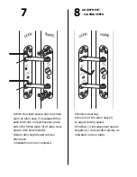
Page 7: ...n keys Installation is now complete 7 Remove dust cap Use one of the allen keys C to adjust closing speed Positive increases door speed Negative reduces door speed as indicated on door plate 8 ADJUSTM...

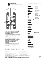
Page 8: ...h com www perko powermatic com US Customer Service 111 East 39th Street Suite 2R New York N Y 10016 Telephone 212 599 5177 Fax 212 818 9552 E mail usa samuel heath com The Perkopower is protected by t...

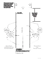
Page 9: ...mp pl la at te e i is s f fo or r r ri ig gh ht t h ha an nd d h hu un ng g d do oo or rs s w wh he en n v vi ie ew wi in ng g c cl lo os si in ng g f fa ac ce e F Fo or r l le ef ft t h ha an nd d h...

Reviews: