© 2009
3
24” ADA-Compliant Series Operation / Installation Manual
PREPARING THE SPACE
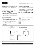
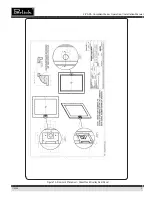
Make sure the installation opening is properly prepared. Refer to
Figure 1 for space dimensions.
CAUTION
If unit is to be installed under a countertop, it is recommended
that the countertop be supported by a structure other than the
unit itself, to prevent damage to the countertop.
IMPORTANT:
For a cabinet door to operate properly, the door must
open a minimum of 100° (see Figure 1). Use a minimum 4-1/2” filler in
corner installations to ensure a 100° opening. Allow enough clearance
in front of the unit for full door swing or shelf pull-out.
IMPORTANT:
Make sure floor under unit is level with the surround-
ing finished floor. Protect a finished floor with plywood, cardboard or
some other suitable material before moving the unit into place. Failure
to do this may result in damage to the floor.
PREPARING ELECTRICAL CONNECTIONS
A 115 volt, 60Hz, 15 amp circuit breaker and electrical supply are
required. A separate circuit is recommended
Follow the National Electrical Code along with local codes and ordi-
nances when installing the receptacle.
All Perlick units come equipped with a NEMA 5-15P, 90° plug with a 5’
cord (minimum) extending beyond the rear of the unit. The electrical
outlet must be flush with, or recessed into, the back wall.
DANGER
ELECTROCUTION HAZARD!
Electrical grounding required. This appliance is equipped with a
3-prong (grounding) polarized plug for protection against pos-
sible shock hazards.
• Never remove the round grounding prong from the plug.
• Never use a 2-prong grounding adapter.
• Never use an extension cord to connect power to the unit.
If a 2-prong wall receptacle is encountered, or a longer power
cord is required, contact a qualified electrician to install the
proper 3-prong receptacle in accordance with applicable electri-
cal codes.
DANGER
Failure to comply with the above electrical guidelines may result
in possible injury/death/fire or loss of property.
UNPACKING AND MOVING THE UNIT
CAUTION
Do not cut cardboard sleeve covering the unit. Cutting may result
in damage to the exterior of the unit.
1. Uncrate the unit outside on a flat level surface. Remove the card-
board sleeve by removing the banding holding the sleeve to the
shipping base. Carefully lift the cardboard sleeve up over the top
of the cabinet.
2. Carefully lift unit off base and onto a hand truck or dolly (this
should be done with a minimum of two people, larger cabinets
may require additional helpers). Make sure unit is balanced on
transporting device. Secure unit to transporting device using soft
flexible strapping. Protect cabinet surfaces with cloth material
where strapping contacts the unit.
3. Before moving unit, secure door to unit with tape to hold the door
closed.
WARNING
A minimum of two people should lift the cabinet off the base to
prevent possible personal injury.
4. Carefully move unit to installation site and place in front of open-
ing.
ANTI-TIP BRACKETS
WARNING
Unit may tip forward if loaded racks/shelves are all pulled out at
the same time. To prevent tipping and provide a stable installa-
tion, the unit must be secured in place with the anti-tip brackets
provided with the unit.
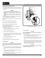
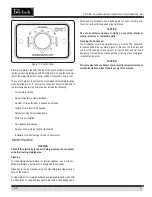
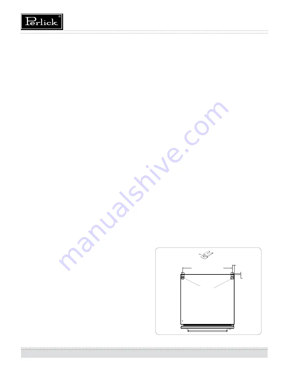
A set of metal anti-tip brackets and #10 x 3/4” screws are supplied with
the unit. The anti-tip brackets, when properly installed, should secure
the rear legs and prevent the unit from tipping forward.
Some installation sites may require modification to provide a secure
surface for attaching the brackets. Refer to Figure 2 for mounting
bracket locations.
IMPORTANT: If installing on a concrete floor, concrete fasteners are
required and are not included in the Anti-Tip kit.
5HDU/HJV
)25&$%,1(76
)25&$%,1(76
'LDPHWHU
$QWLWLSEUDFNHW
3DUW
Figure 2. Anti-Tip-Over Bracket Mounting


