background image

13

Perlick.is.committed.to.continuous.improvement..Therefore,.we.reserve.the.right.to.change.specifications.without.prior.notice.

MAINTENANCE.AND.TROUBLESHOOTING

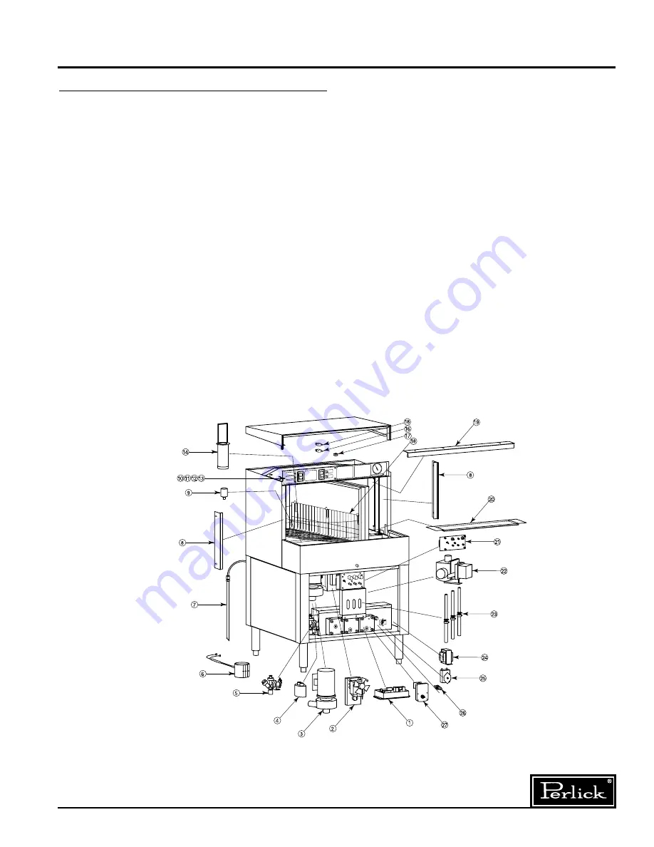
Replacement Parts 

 ITEM 
  NO. 

dESCRIPTION 

PART NO.

.. 1.

Glasswasher.Control.Kit.

55042

.. 2.

Spray.arm.drive.motor.

52536

.. 3.

Wash.pump.

50445

.. 4.

Pump.motor.capacitor.

52528

.. 5.

Water.inlet.valve.

52652-1

.. 6.

Band.heater.

52669-1

.. 7.

Rinse.aid.pickup.tube.assembly.

52626A-B

. .

Detergent.pickup.tube.assembly.

52626A-R

. .

Sanitizer.pickup.tube.assembly.

52626A-W

.. 8.

Divider.side.seal.

52696

.. 9.

Wash.water.level.switch.

R54978-1

. 10.

Start/Wash.switch.

55003-1

. 11.

Power/drain.(on/off/drain).switch.

55004-1

. 12.

Red.light.

54809

. 13.

Amber.light.

54810

. 14.

Wash.tank.filter.

52492

. 15.

Safety.switch.-..250".quick.connect.

54995-1

. 16.

Safety.switch.-..187".quick.connect.

54996-1

. 17.

Roller.bearing.for.divider.lock.

C12698-1

 ITEM 
  NO. 

dESCRIPTION 

PART NO.

. 18.

Glass.rack.

50470-2

. 19.

Top.divider.seal.

52692

. 20.

Top.wash.tank.screen.

50588

. .

(For.Serial.Nos..to.443593.only)

. 20A..

Top.wash.tank.screen.

R50614

. 21.

Chemical.system.control.board.

50453

. 22.

Drain.valve.

50451

. 23.

Chemical.system.sight.tube.kit.

52714A

. 24.

Transformer.

52566A

. 25.

Temperature.control.

54153A

. 26.

Fuse.holder..

54938-1

. .

12.amp.fuse.

54939-1

. 27.

Chemical.pump.gear.motor.

52537

PARTS NOT ShOwN

. .

Chemical.bulkhead.fittings.

R54976

. .

Amber.chemical.sight.tube.light.

54790

. .

Flat.strainer.

54965-1

. .

Clean-out.plugs.for.spray.arms.

R54900-1

. .

1

4

".ID..chemical.pump.squeeze.tube.

52679-1

. .

3

16

".ID.chemical.pump.squeeze.tube.

52681-1

. .

1

8

".ID.chemical.pump.squeeze.tube.

52680-1

. .

Seal.kit.

R54965

Summary of Contents for PKBR24

Page 1: ...ne Operation Cycle Sequence 12 Replacement Parts 13 Electrical Connection Diagram 14 Adjusting Chemical Concentrations 15 Calibrating the Chemical System 15 8300 West Good Hope Road Milwaukee WI 53223...

Page 2: ...er installation or failure to follow operating and maintenance procedures Examples of the forego ing but without limitations are 1 Damage to machine resulting from excessive concentrations of chlorine...

Page 3: ...air gap Plumbers Hookup Kit Includes water hammer arrestor stop valve and union Important Failure to install the Glasswasher with Plumbers Hookup Kit can damage the hot water solenoid valve Machine f...

Page 4: ...ntaining Low water conditioners Water with more than 15 GPG will require a water softener It cannot be conditioned economically with chemicals Failure of parts caused by hard water are not covered und...

Page 5: ...h to ON CHECK Waterlevel inside the tank Level should be at top of overflow tube Priming The Chemical System The chemical system prime buttons are located in the chemical control panel Each of the thr...

Page 6: ...during reassembly Although the components appear to be identical they are not If the entire housing is removed it must be reinstalled in exactly the same position to avoid stripping the spider 5 Remov...

Page 7: ...Controls detergent concentration with three pre calibrated settings 1 Lowest Concentration 2 Medium Concentration 3 Highest Concentration Your water hardness detergent strength and amount of water con...

Page 8: ...t The fan shaped spray cleans and rinses the exterior of the glasses 6 DIVIDER Holds two removable racks The divider can be manually rotated in either direction but must be parallel to the front of th...

Page 9: ...action terminates the wash cycle and then the glass ware will not have been properly washed and or sanitized 5 When the yellow Cycle Complete light comes on this indicates that the glasses in the wash...

Page 10: ...be kept in the ON position except during cleaning POWER SWITCH When switch is in the OFF position the Chemical OFF light on the instrument panel will be illuminated 2 DETERGENT CONTROL KNOB Controls d...

Page 11: ...running clean the load area and exterior of the machine with a damp cloth and wipe dry Replenish chemicals if required See warning 8 Press the lower portion of Power drain on off drain switch for 10...

Page 12: ...Cycle Sequence At the beginning of the wash cycle the water in the tank is charged with detergent After the cycle is completed the detergent water is dumped down the drain The sanitizing rinse cycle...

Page 13: ...54810 14 Wash tank filter 52492 15 Safety switch 250 quick connect 54995 1 16 Safety switch 187 quick connect 54996 1 17 Roller bearing for divider lock C12698 1 Item No Description Part No 18 Glass r...

Page 14: ...STEM CONTROL PANEL SIGHT GLASS LIGHTS WHITE WHITE WHITE WHITE 24 VDC 24 VDC 1 7 8 11 12 6 5 2 1 4 3 2 24 VDC 24 VDC 28 VAC 1 POWER CORD GROUND TRANSFORMER WHITE WHITE WHITE GREEN GREEN WHITE BLUE BLUE...

Page 15: ...nds 4 X Position 1 If more adjustment is required the chemical sys tem must be recalibrated See Chemical System Calibrating procedure Calibrating the Chemical System IMPORTANT READ BEFORE BEGINNING Re...

Page 16: ...oad Milwaukee WI 53223 Phone 414 353 7060 Fax 414 353 7069 Toll Free 800 558 5592 E Mail Perlick Perlick com www Perlick com Perlick is committed to continuous improvement Therefore we reserve the rig...

Reviews: