Model 5210D User’s Manual
Doc. SE-MAN-050 REV 00
Page 8 of 25
©2017 Perma Pure LLC. All rights reserved. Specifications subject to change.
INSTALLATION
Hardware required for installation
(4) ¼-20 mounting screws
For stainless steel sample lines, 2 inches of 3/8” Teflon tube
Peristaltic drain pump, dual head
Mounting
The Classic Model 5210D Thermo-Electric Cooler should be installed away from heat sources in a well
vented area.
NOTE: The operational stability of the cooler dew point is influenced by the stability of the
ambient temperature.
For proper operation, the ambient temperature cannot exceed 40°C (104°F). At, or close to the maximum
ambient temperature, the cooler will not be able to control the temperature to reduce the dew point of the
sample gas to the 4°C set point. This will result in compromised operation and water slip or carryover,
possibly into the analyzer. Also, at or near this temperature, the cooler will be running “full on” and Peltier
life will be greatly reduced.
CONNECTIONS
Sample and Drain
1.
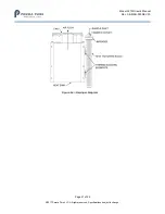
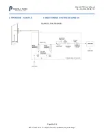
Connect the sample inlet to the
3/8
” tube fitting shown in figure 3 below.
NOTE: If using heated stainless steel sample line, add 2 inches of Teflon tubing at the heat exchanger
inlet fitting, and connecting it to the heated line. This isolates the heated line from the heat exchanger
and prevents excessive heating of the heat exchanger, possibly overloading the cooler.
2. Connect the sample outlet to the
1/4
” tube fitting shown in the figure.
3. Connect the peristaltic pumps to the ¼” barbed tube fittings at the base of the impinger.
NOTE: Do not reduce the size of the condensate tubing since doing so restricts water flow resulting in
water carryover into the sample.
Figure 3: Model 5210D Cooler


