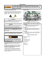
background image

3. 

Brake Systems


A


Front Brake System. 
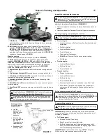
Components: Brake Lever with Lock, Front Brake Cable 1, 

Front Brake Cable 2, Band Brake, Brake Drum, Band Tension 

Spring, Sheath Brake pin, Rod Brake pin, 1 washer, Lock Nut. 

 

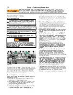
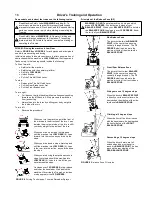
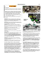
Park a fully loaded machine on level ground free from 
obstructions and bystanders. Start engine. 

 

While in 

NEUTRAL

, push the machine forward. No unusual 

drag should be felt. 

 

Pull and release the Front Brake Lever several times. 
Ensure that the lever operates smoothly and snaps back 

completely when released. The operating force on the 

Lever must not exceed 

25 POUNDS 

of force.       

 


Shift into 

HIGH GEAR

, accelerate to full speed, and pull 

the Front Brake Lever.                                    Confirm that 

the machine stops smoothly in less than 

8 FEET

 and the 

Brake does not lock up. Brake band must not over 

heat 

nor cause unusual drag. 

Rear Brake System.                              Components: Brake 

Lever with Lock, Rear Brake Cable, Band Brake (2), Brake 

Drum (2), Band Tension Spring (2), Sheath Brake pin (2), Rod 
Brake pin (2), washer (2), Lock Nut (2). 

 

Pull and release the Rear Brake Lever several times.  

Confirm that the lever operates smoothly and snaps back 
completely when released. The operating force on the Lever 

must not exceed 

25 POUNDS 

of force.            

 

While in 

NEUTRAL

, push the machine forward. No unusual 

drag should be felt. Shift into 

HIGH GEAR

, accelerate to full 

speed, and pull Rear Brake Lever. 


Confirm that the machine stops smoothly in less than 


FEET

. Confirm that both Brakes drag equally without 

causing  a change of course, left or right. Brake band must 

not over heat nor cause unusual drag. 

C  Both Front and Rear Brake Systems 

 

  Shift into 

HIGH GEAR

, accelerate to full ground speed and 

pull both brake levers. Confirm that the machine stops in less 

that the length of the machine. 

D  Parking Brake System.                             Components: Front 

Brake System and Rear Brake System. 

 

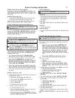
Drive the fully loaded machine up a 

17 DEGREE 

slope, stop 

and lock both Brake Levers.                               Confirm that 

brakes hold the machine in place. 

 

Drive the fully loaded machine down a 

17 DEGREE 

slope, 

stop and lock both Brake Levers.                               Confirm 

that the brakes hold the machine in place. 

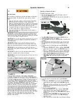
SmartSteer Brake Assist Steering.                             

Components: SmartSteer Handle Assembly, Steering Brake 
Cable (2), Band Brake (2), Brake Drum (2), Sheath Brake pin 

(2), Rod Brake pin, Cable (2), Lock Nut (4),. 

 

Park the fully loaded machine on level ground free from 
obstructions and bystanders. Start engine.   

 

Check right and left Steering Cable condition. Confirm that 
both cables are tight. 

 

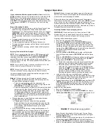
Check SmartSteer Handle assembly by moving the Handles 
in opposite directions.                             Make sure Handles 

move smoothly and only in opposite directions of each other 
with minimal free play and that  Rubber Mounts are intact. 
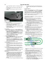
 

Shift into 

HIGH GEAR 

and drive straight forward..                               

Confirm that the machine travels in a straight line without 

pulling right or left and no unusual noise is detected. 

 

Shift into 

HIGH GEAR 

and maneuver through a series of 

lock-to-lock figure eights.                               Confirm that 

the machine steers out of the turns with no more than 

30 

POUNDS 

of force required and the Brake Band 

temperature does not exceed 

115 DEGREES 

Fahrenheit 

(46 degrees Celsius), and that the machine does not make 

any unusual noises. 

Phase X: Additional Service Training


Trainee should be instructed on any additional service he will be 

required to perform on the Triumph such as, changing Engine and 

Clutch oil, greasing, etc. Refer to Service Manual for scheduled 
service requirements and details. 

Phase IX: Loading and unloading the machine on a Transport. 

Trainee must be instructed how to safely load and unload the 

Triumph from a transporting vehicle. 

Read Safety Manual 

WARNING 16

, Transporting before 

attempting to load or unload the Triumph from a transport. 


Phase XI: Testing Safety Devices.  


If any Safety Device fails a test, adjust, repair or replace the 
component before operating the machine. 
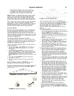
1. 

Throttle/Clutch/ Operator Presence Control 


Components: Throttle Lever, Throttle Cable, Auxiliary Throttle 

Return Spring, Multifunction Display (Tachometer), Drive Belt, 

Idler Pulley, Idler Tension Spring, Transaxle, Honda Engine 

and components: Honda carburetor and linkage, Honda 
Governor Spring, Honda Throttle Spring, Honda Throttle 

Return Spring, and Honda Clutch. All components must be in 

place and functioning normally. 

 

Park on level ground free from obstructions and bystanders. 
Lock both Brake Levers. 

 

Pull and release Throttle Lever several times.         Ensure 
that the lever moves smoothly and easily and snaps back 

when released.  

 

Start engine and verify that the engine speed increases and 
decreases rapidly and the clutch engages and disengages 

quickly. 

 

Engine idle.                                    Ensure the engine idles 
smoothly without dying and the idle speed on the 

Multifunction Display does not exceed 

1650 RPM

 

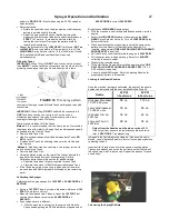
Engine Top end speed. Pull and hold Throttle/Clutch Lever.                              
Confirm that the top end speed is 

3450 RPM

 

Clutch engagement. Shift into 

LOW GEAR

 and gradually 

accelerate engine.                                 Confirm that the 

machine does not move when shifted, or creep at Idle 

speed. The Clutch shall engage smoothly as the engine is 
accelerated and propel the machine forward at 

3.5 MPH 

at 

full acceleration. No unusual noise should be detected. 

2. 

Neutral Safety Switch System (NSSS) 


Components: NSSS Module, Kill Switch, Neutral Switch, Honda Kill 

Wire, Ground wire, Wire Harness and terminals. 

 

Park on level ground free from obstructions and 
bystanders .  

 

Lock both Brake Levers, shift into 

NEUTRAL 

and start 

engine. 

 

Turn Engine off with Kill Switch. 


Confirm that the engine starts and Kill Switch works. 

 

Shift into LOW GEAR and repeat the previous test.      
Confirm that the engine does not start in gear. 


Read Safety Manual 

WARNING 19

, Maintenance and Service 

before starting or operating the Triumph. 


Read Safety Manual 

WARNING 5

, Safety Devices before 

starting or operating the Triumph. 


Driver’s Training and Operation 

18 

Summary of Contents for E1E

Page 1: ...UR SUPPORT HOTLINE AT 800 346 2001 SUPPORT PERMAGREEN COM OR AT WWW PERMAGREEN COM PermaGreen Triumph Spreader Sprayer Operator s Manual Model E1E with Serial Number 170001 and Above Triumph E1E Seria...

Page 2: ...of the manual When a manual revision is provided insert the revised pages in the manual Record the revision number the date the revision was inserted in the manual and provide your initials or signatu...

Page 3: ...as Starting and General Instructions 15 e Driving Techniques and Principles 16 f Driving on Hillsides and Daily Service 17 g Testing Safety Devices 18 5 Spreader Operation 21 24 a Spreader Controls an...

Page 4: ...Page left intentionally blank iii...

Page 5: ...nent part of the machine It must be available at all times to all of the operators and persons servicing the machine Should the machine be resold this manual and service records are to remain with it...

Page 6: ...ly assembled and tested damage may have occurred in transit or storage A PermaGreen Servicing Dealer or the purchaser of the Triumph shall perform the Pre Operation Inspection and complete and fax or...

Page 7: ...cing nor vibration should cause the Deflector to change position Fully Loaded Brake Inspection Place planking on top of the Screen in the Hopper to protect the agitator and the screen Put 150 POUNDS o...

Page 8: ...Page left intentionally blank 4...

Page 9: ...er leaving Read additional Safety Labels on this machine B WARNING Before operating Training is required Read operator s Manual Read safety instructions Read all machine safety labels Shields must be...

Page 10: ...Machine WARNING Labels Refer to FIGURE 2 SAFETY MANUAL 6 R WARNING Improper operation and improper maintenance of this machine may cause death or serious injury DO NOT operate the machine if Engine s...

Page 11: ...eep heat sparks and flame away Never refuel or drain indoors Use only an ap proved container ALWAYS close fuel valve when transporting the machine Read engine Owner s Manual Machine Information Labels...

Page 12: ...umph in LOW GEAR As the trainee progresses to more advanced phases of training the degree of difficulty may be increased but at each phase the initial training must begin on terrain that has a low deg...

Page 13: ...ction Equipment refer to Pesticide Label when using compressed air or water to clean the machine Regulate the pressure to 29 PSI 200 Kilopascals 6 Inspecting work area Prior to operating carefully ins...

Page 14: ...Back in Reverse Gear with the Throttle Clutch engaged using the brakes as necessary 13 Avoiding slipping or tripping injury Use caution when riding on and getting on and off the Triumph Keep a firm g...

Page 15: ...ll side This is the preferred angle for driving on gentle slopes When pointing across an incline continued Recommendations for driving across a hillside Lean uphill to provide better balance for you a...

Page 16: ...Safety Manual WARNING 13 Reverse Operation for required precautions while operating the Triumph in reverse If there is not adequate standing room for the operator on the Transport platform the machine...

Page 17: ...e Service Manual 19 Pesticide Safety The improper use handling application and disposal of pesticide products applied by this machine may cause death or serious injury Read and follow product label an...

Page 18: ...Handlebars permitting them to drop down for the convenience of the operator and to permit the machine to used as a walk behind unit The Handlebars automatically lock in the down position Pushing the...

Page 19: ...to Neutral Turn Kill Switch OFF When leaving the machine unattended close Fuel Valve Never leave the machine unattended on a slope where someone could disengage the Brakes and the machine could roll P...

Page 20: ...front of the driver is even with the handlebars he has reached the front sideline of the FRONT BALANCE ZONE Descending a 15 degree slope When the driver s arms are full extended and he must squat to...

Page 21: ...Third Hole Slide plate and linkage Engine cooling fins Blower housing inlet Starter carbure tor governor linkage Honda Throttle Lever Throttle Lever and cable Lubricate and protect the following using...

Page 22: ...o unusual noise is detected Shift into HIGH GEAR and maneuver through a series of lock to lock figure eights Confirm that the machine steers out of the turns with no more than 30 POUNDS of force requi...

Page 23: ...ds 1 4 INCH Rotate each tire so the valve stem is in the 12 O CLOCK position and check pressure Confirm that tire pressure is 12 PSI 83 Kilopascals and fluid is visible 7 Machine Safety Label Visual T...

Page 24: ...Page left intentionally blank 20...

Page 25: ...rt spreader operation by pushing the Hopper Lever C forward to the OPEN position To stop spreader operation pull the Hopper Lever rearward to the CLOSED position Spreader Rate adjustment The HIGH GEAR...

Page 26: ...of the machine move the Third hole Lever forward to increase the opening of the Third hole Adjuster Plate Spreader Operation NOTE For proper spreading the engine RPM measured with the machine in NEUTR...

Page 27: ...nt Knob against the Hopper Lever and tighten the knob Close and open the Hopper several times and confirm hole opening Adjust Third hole setting Without changing the Rate Adjustment Knob setting open...

Page 28: ...time required to travel the 143 FOOT 44 meter turf course The normal time is approximately 20 seconds 1 seconds With the machine operating in LOW GEAR at full throttle RECORD THE TIME required to cove...

Page 29: ...ast D trim E for use while in LOW GEAR and a second pair of low drift nozzles broadcast F and trim G for use in HIGH GEAR If the Half Gallon Nozzle Kit is installed the LOW GEAR Broadcast Nozzle is re...

Page 30: ...d resemble the 3 FOOT spray If your calibrated effective spreader width is 8 feet install the 30 PSI unloader cap from the Unloader Valve included in the 8 FOOT Spray Kit supplied with the machine and...

Page 31: ...rayer Calibrate machine ground speed to 143 FEET in 20 SECONDS 1 SECOND Set up a 143 FOOT long test course Measure a distance of 143 FEET 44 meters over turf Measure the elapsed time it takes to trave...

Page 32: ...use the Spot Sprayer is carried in a machine mounted bracket Triumph provides room for an optional second Spot Sprayer The Spot Sprayer holds enough spray to cover approximately 500 ft2 46 5 meters2...

Page 33: ...ilizer and Ethanol Treatment additive in every tank to prevent ethanol related fuel problems STA BIL is the only approved fuel stabilizer for use in PermaGreen equipment Use PREMIUM unleaded fuel NEVE...

Page 34: ...nal Transaxle damage Do not attempt to repair Brakes Stop too fast Brake Cable adjusted too tight Brake Band and Drum dirty Something caught in Brake Band and Drum Rear Wheel Hub low on grease Stop to...

Page 35: ...roduct does not flow from Hopper See Spinner Platter does not turn Engine RPM incorrect Sprayer No Spray output Tanks empty Spray system not primed Suction Valve closed Clogs Nozzle Strainer Tank Stra...

Page 36: ...Page left intentionally blank 32...

Page 37: ...k Hopper opening Rate Adjustment Knob Check and adjust the Spray Nozzle alignment as necessary Check and top off engine oil Check and top off clutch oil Check for loose or missing fasteners or parts c...

Page 38: ...ne Safety Labels Replace worn or damaged footpads Perform all scheduled maintenance as directed in the Service Manual Tires are filled with pressurized diluted RV antifreeze to provide ballast for a l...

Page 39: ...the Triumph Read Safety Manual WARNING 5 Safety Devices now FIGURE 19 Checking engine oil FIGURE 20 Check clutch oil Level Checking clutch oil Refer to FIGURE 20 Remove clutch OIL FILLER CAP DIPSTICK...

Page 40: ...DO NOT over speed engine Replacing Throttle Lever Remove Handgrip Loosen Lever tensioning Screw Remove cable Replace Throttle Lever in reverse order Replacing Throttle Cable Remove Handgrip Loosen Lev...

Page 41: ...action and readjust as desired 37 Brake adjustment Refer to FIGURE 25 To increase braking loosen jam nut and extend Turnbuckle Adjuster Test braking and adjust as necessary Tighten jam nut To decrease...

Page 42: ...Plumbing and Electric Schematics 38 FIGURE 25 Plumbing Diagram A Starting module B Neutral switch C Ground to engine D Kill switch E Engine Magneto FIGURE 26 Wiring Diagram...

Page 43: ...A BIL Fuel Stabilizer and Ethanol Treatment additive into all fuels used Premium unleaded preferred Regular unleaded minimum NOTICE NEVER use E85 or other high ethanol fuel Oil Specifications on your...

Page 44: ...Supreme Inc with prior notification of the need for Warranty Service or Buy Back Return a Warranty Claim Form to PermaGreen Supreme Inc along with the claimed defective part s if required within 30 D...

Reviews: