Spreader Operation
IMPORTANT: The Spreader requires periodic calibration and
adjustment to verify the spreader pattern and to verify the correct
product delivery rate. Improper application of products can damage
turf or reduce the efficacy of applied products.
IMPORTANT: Check and adjust Spreader pattern daily, prior to
treating each lawn, and as needed to verify that the Spreader is
spreading properly.
IMPORTANT: Whenever you change products or rates of
application and at one-week intervals, or more frequently during
heavy use, verify that calibration is still valid. Adjust as necessary.
IMPORTANT: You should regularly compare the amount of
product used to the number of square feet covered to verify correct
delivery rate.
IMPORTANT: Use caution when spreading near desirable
vegetation or painted surfaces to avoid damage.
IMPORTANT: Use caution when spreading in windy conditions
to avoid damage.
Description of Spreader features, controls, and operation
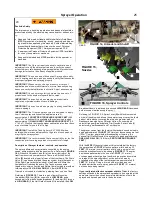
This machine uses a familiar 3-hole cyclone type spreader
mechanism, and comes factory set to broadcast spread a pattern
width of
14 ± 1 FEET
(4.3 ± 0.3 meters). Using a
7 ± 1 FOOT
(2.1 ±
0.3 meters) overlap travel pattern provides an even distribution of
most products.
NOTE
: Actual spread pattern width and overlap
may vary based on your calibration (refer to Spreader Calibration in
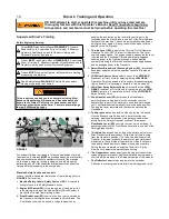
this section). Referring to
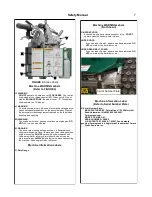
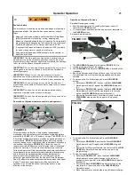
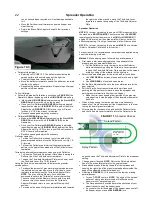
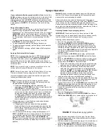
FIGURE 10
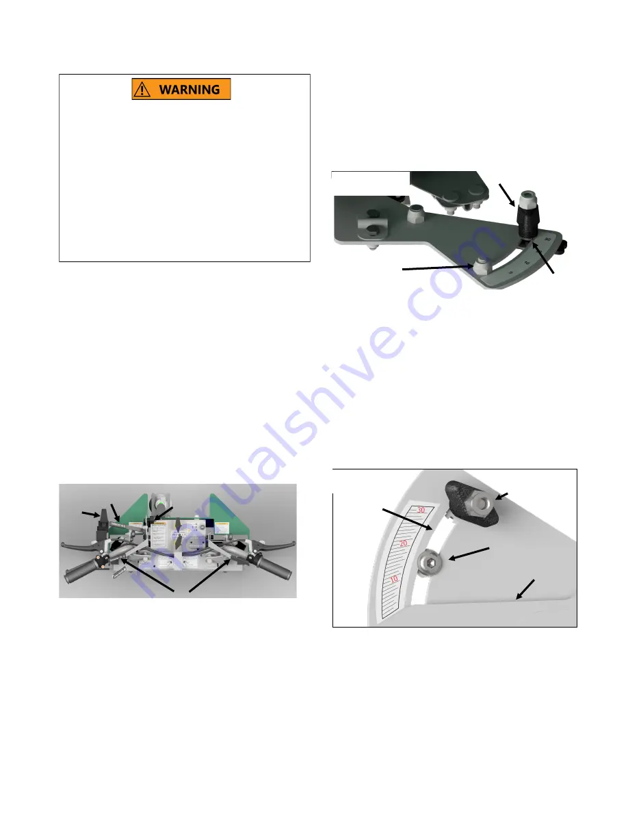
: A Deflector Lever (A)
remotely controls a Deflector to cut off the right side of the spread
pattern for trimming. A Third-hole Lever (B) remotely controls a
Third-hole Adjustment Plate that should be used with the Deflector
to compensate for the amount of product required while trimming
and to balance the spreader pattern for even distribution. An
opening and closing Hopper Lever (C) remotely controls the
delivery of granular material from the Hopper. A Rate Adjustment
Knob (D) adjusts the amount of product delivered when the hopper
is open. The sprayer can be operated at the same time the
spreader is in use, and the seven-foot overlap pattern is also
effective for the sprayer.
Operation of Spreader Controls
Spreader Opening and closing.
Start spreader operation by pushing the Hopper Lever (C)
forward to the
OPEN
position.
To stop spreader operation, pull the Hopper Lever rearward to
the
CLOSED
position.
Spreader Rate adjustment.
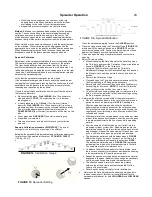
The
HIGH GEAR
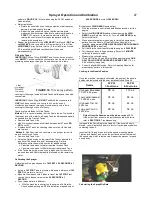
Spreader Rate Adjuster (
FIGURE 10.1
) is
located at the lower front of the hopper.
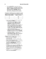
The
LOW GEAR
Rate Adjuster (
FIGURE 10.2
) is located on the
Handlebar.
Each Rate Adjuster has a stop bolt that is to be Pre-set to the
Pre-calibrated rate for the product being applied and the gear
selected.
To spread at the Pre-Calibrated and Pre-set
HIGH GEAR
setting:
Referring to
FIGURE 10.1
, position the Black
HIGH GEAR
Rate Adjuster Knob (E) against the
HIGH GEAR
stop bolt
(F)
Referring to
FIGURE 10.2
, position the Black
LOW GEAR
Rate Adjuster Knob (D) all the way forward in the curved
slot on the
LOW GEAR
Rate Adjuster Bracket (I).
Moving the Fertilizer lever (J) forward into contact with the
HIGH GEAR
stop opens the hopper to the desired
setting.
To spread at the Pre-Calibrated and Pre-set
LOW GEAR
setting:
Referring to
FIGURE10.2
, position the Black
LOW GEAR
Rate Adjuster Knob (D) against the
LOW GEAR
stop bolt
(H).
Moving the Fertilizer lever forward into contact with the
LOW
GEAR
Rate Adjuster Knob opens the hopper to the
proper setting.
To clear a clogged spreader port:
Referring to
FIGURE 10.1
, move the Black
HIGH GEAR
Rate Adjuster Knob counterclockwise to the left most
position in the curved slot in the
HIGH GEAR
Rate Adjuster
Bracket (G).
Position the Black
LOW GEAR
Rate Adjuster Knob all the
way forward in the curved slot on the
LOW GEAR
Rate
Adjuster Bracket.
Move the machine to an area where any fertilizer discharge
21
Pesticide Safety
The improper use, handling, application, and disposal of pesticide
products applied by this machine may cause death or serious
injury.
Read and follow product label and Material Safety Data Sheet
(MSDS) precautions for handling, mixing, applying, and
disposing of pesticides applied by this machine. Some materials
may present health hazards that will require the use of Personal
Protection Equipment (PPE). Always wear required PPE.
Keep required Personal Protection Equipment (PPE) available
for use by the operator or mechanic at all times.
Keep pesticide labels and MSDS available for the operator or
mechanic at all times.
20
FIGURE 10
A
B
C
D
H
D
I
J
FIG.10.2
FIGURE 10.1
E
F
G

