


IMPORTANT: The Sprayer requires periodic calibration and
adjustment to verify the sprayer pattern and to verify the correct
product delivery rate because improper application of products can
damage turf or reduce the efficacy of applied products.
IMPORTANT: Check and adjust Broadcast Spray pattern daily,
prior to treating each lawn, and as needed to verify that the nozzles
are properly aligned and spraying properly.
IMPORTANT: Whenever you change products or rates of
application and at one-month intervals, or more frequently during
heavy use, verify that calibration is still valid. Adjust as necessary.
IMPORTANT: You should regularly compare the amount of
product used to the number of square feet covered.
IMPORTANT: Use caution when spraying near desirable
vegetation or painted surfaces to avoid damage.
IMPORTANT: Use caution when spraying in windy conditions
to avoid damage.
IMPORTANT: The Triumph spray system is designed to apply
Low Volume spray solutions at the application rate of
approximately 1 QUART PER THOUSAND SQUARE FEET (0.95
L / 93 m
2
). An optional kit is available with nozzles sized to apply
approximately ½ GALLON PER THOUSAND SQUARE FEET (1.9
L / 93 m
2
). Products that require higher application rates than these
are not suitable for use in the Triumph.
IMPORTANT: Install the Tank Agitator Kit T 000593 when
working with water insoluble products. High rate of such products
may clog the spray system.
IMPORTANT: It is recommended that a compatibility jar test be
conducted prior to mixing any product or products in Triumph.
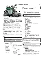
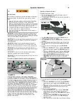
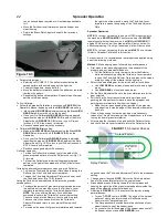
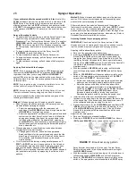
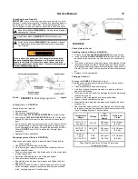
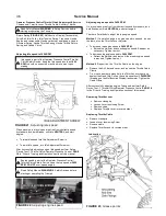
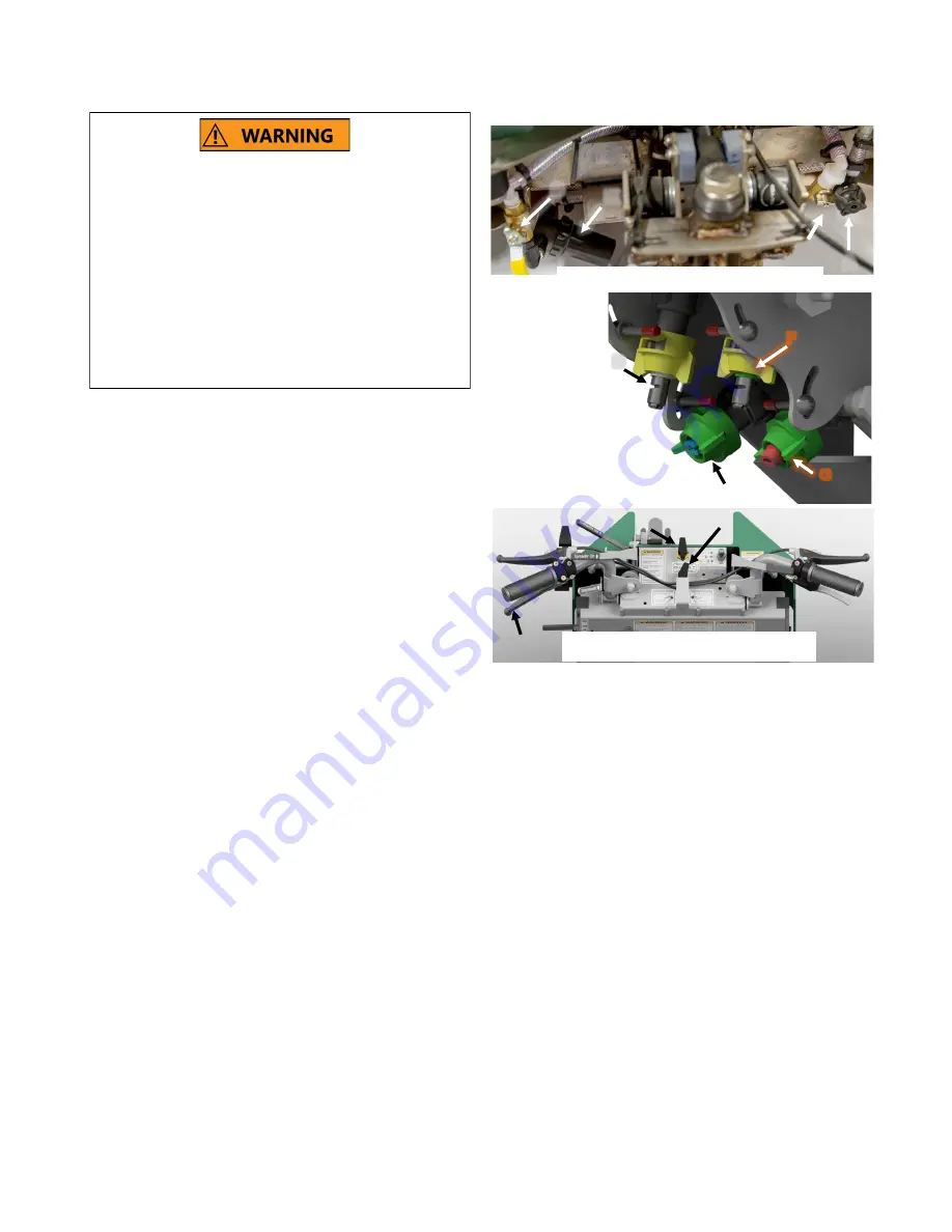
Description of Sprayer features, controls, and operation
The spray pattern and spray rate are controlled by the engine
speed, pump pressure, and the nozzle orifice. Referring to
FIGURE
14
: A Pressure Unloader Valve (
A
) at the lower right rear of the
front frame controls pump pressure. There is a Suction Shutoff
Valve (
B
) located at the lower left rear of the front frame. The Drain
Valve (
C
) can be used to flush the spray system, drain the tanks or
fill the Spot Sprayer bottle (included). Line Strainer K filters the
liquid before it reaches the pump. The Tanks are connected
together by common Suction and Return flow plumbing to provide a
total capacity of
12 U.S. GALLONS
(45.4 liters).
NOTE: The
Triumph is not capable of selectively drawing from only one Tank.
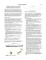
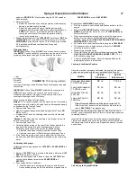
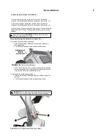
Referring to
FIGURE 15
: There is a pair of low drift nozzles
(broadcast (
D
) & trim (
E
)) for use while in
LOW GEAR
, and a
second pair of low drift nozzles (broadcast (
F
) and trim (
G
)) for use
in
HIGH GEAR
. [If the Half Gallon Nozzle Kit is installed, the
LOW
GEAR
Broadcast Nozzle is replaced by a second
HIGH GEAR
Nozzle and
both are used simultaneously to spray.]
Referring to FIGURE 16: A Spray Lever (
H
) with lock is mounted
on the left handle which allows the operator to spot spray the liquid
product while blanket covering the area with granular product.
Dashboard mounted Spray Selector Valves (
I
) control which
selects High gear Broadcast and Trim Nozzles. Spray Valve (
J
)
selects Low gear Broadcast and Trim Nozzles.
The sprayer comes from the factory with standard nozzles sized to
apply approximately
1 QUART
(.95 liters) per thousand square feet
((93 m
2
) in either gear whether broadcasting or trimming. [An
optional Half Gallon Nozzle Kit is available to apply approximately
ONE-HALF GALLON
(1.89 liters)
PER THOUSAND SQUARE
FEET.
]
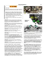
With the
20 PSI
Pressure Unloader Valve installed at the factory,
the sprayer has a
7-FOOT
effective pattern width and an
11
FEET
(3.4 meters) overall pattern width using a single front
mounted broadcast nozzle, as shown in
FIGURE 17
. The spray
distribution pattern allows the use of a
7-FOOT
(2.1 meter)
overlap spreader travel pattern to achieve an even and complete
coverage of the sprayed product on the entire turf area by
overlapping the edge of the last spray pattern approximately
2
FEET
(.61 meter). Using a trim nozzle provides an even
finished distribution over a spray pattern of
3-FEET
(.91 meters)
on the surface being treated.
If your calibrated effective spreader width is 7 feet
, the factory
settings will enable the sprayer and spreader to be operated at the
same time to provide even and complete distribution of both the
sprayed and spread products to the entire area.
Sprayer Operation
25
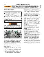
Pesticide Safety
The improper use, handling, application, and disposal of pesticide
products applied by this machine may cause death or serious inju-
ry.
Read and follow product label and Material Safety Data Sheet
(MSDS) precautions for handling, mixing, applying, and dispos-
ing of pesticides applied by this machine. Some materials may
present health hazards that will require the use of Personal
Protective Equipment (PPE). Always wear required PPE.
Keep required Personal Protection Equipment (PPE) available
for use by the operator or mechanic.
Keep pesticide labels and MSDS available for the operator or
mechanic.
20
FIGURE 16, Sprayer Controls
H
I
J
FIGURE 15,
Nozzles
F
G
D
E
K
C
B
A
FIGURE 14, Unloader and Shutoff


