

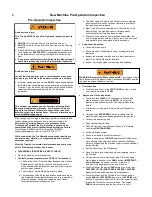


Neutral Safety Switch Inspection
Following the starting procedures above attempt to start the
machine in
LOW GEAR
,
HIGH GEAR
and
REVERSE
. It
SHALL
NOT
start in gear.
IF THE MACHINE STARTS IN
ANY GEAR, DO NOT CONTINUE THE TEST OR
OPERATE THE MACHINE Contact PermaGreen support
and/or refer to the Troubleshooting Section for details.
Drive and Brake Systems Inspection
Remove the chock blocks and unlock both Brake Levers.
On a paved parking lot, shift into
LOW GEAR
and pull the
Throttle Lever. The machine should smoothly accelerate to
about
3.5 MPH
.
Pull the Rear Brake Lever. Both rear wheels should drag
equally without causing a change of course, left or right.
Accelerate again and carefully pull the Front Brake Lever.
When applied, the front brakes shall not lock up.
Stop. Repeat the acceleration and brake tests in
HIGH
GEAR
. Top speed shall not exceed
5 MPH
.
At top speed, the Rear Brakes alone shall bring the machine
to a smooth stop within
8 FEET
.
The Front Brakes alone shall do the same.
Appling both Front and Rear Brakes together should stop
the machine in less than the length of the machine.
Shift into
REVERSE GEAR
. The machine should back up
under power.
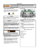
Spray System Inspection (see PAGE 25 for locations)
Fill the tanks with water. Open the Suction valve and the Fill
Valve. Place a collection bucket under the Fill Valve. Start
the engine and run it at high speed until the Spray System is
primed. Close the Fill Valve.
NOTE: To prevent freeze
damage, the Spray System has been tested using a
diluted RV antifreeze/water solution, and then drained.
Many local regulations permit small quantities of RV
antifreeze to be disposed of in the sanitary sewer system.
Check your local regulatory agency for proper disposal.
Check for and repair any leaks.
With the collection bucket in place, spray through each
nozzle individually to purge the lines of RV antifreeze/water
solution.
Adjust the position of each nozzle. Refer to Spray System
Instructions.
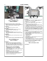
Spreader System Inspection (see PAGE 21 for locations)
Operate the Hopper Lever to completely open and close the
hopper holes. Vibration shall not cause the Hopper Lever to
move.
The Rate Control Knob is in place.
Operate the Third Hold Lever to close or reveal the Third
Hole in the hopper.
Operate the Deflector Lever. Neither bouncing nor vibration
should cause the Deflector to change position.
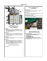
Fully Loaded Brake Inspection
Place planking on top of the Screen in the Hopper to protect
the agitator and the screen.
Put
150 POUNDS
of weight into the Hopper.
With the tanks filled, repeat the braking tests stated above in
the Drive and Brake System Inspection.
Drop the handlebar and walk up a
17 DEGREE
incline, stop
the machine and apply and lock both Front and Rear
Brakes. The brakes shall prevent the machine from moving.
Repeat the test heading down the incline.
Steering System Inspection
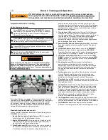
With the machine fully loaded, drive through a series of lock
to lock figure eights for 5 minutes. The steering effort to
come out of the tightest turn shall be less than
30 Pounds
of
force.
The Steering brakes bands shall not overheat.
Delivery Instructions for Dealers and/or purchasers
Review the Operator’s Manual, Safety information,
operating instructions, and controls with the purchaser.
Purchasers shall be made comfortable with the proper
operation of the Triumph prior to using the machine.
The Triumph Warranty Registration Form shall be
completed, signed and dated by the purchasing Dealer and
Inspector, and faxed or mailed to PermaGreen within
14
DAYS
. PermaGreen, 5609 Murvihill Rd, Valparaiso IN
46383 or (fax) 219-476-7113.
NOTE: The limited Warranty is not valid unless a
completed Triumph Warranty Registration Form is
received by PermaGreen with 30 DAYS of purchase
.
Dealer Delivery Instructions and Obligations
1) Complete the New Machine Pre-Operation Inspection.
2)
Complete and return to PermaGreen the Warranty
Registration Card within 10 DAYS.
NOTE: If Dealer is unable to complete the Inspection or
Warranty Registration Card, Dealer shall notify the
customer of their obligation to do so.
3) Dealer shall provide the purchaser:
A) Verbal instructions of their obligation to read the Triumph
Operator’s Manual and the Safety Instructions contained
therein, as well as, to conduct the New Machine Pre-
Operation inspector if not performed by the Dealer.
B) The Triumph Operations Manual with the serial number
that matches the Triumph being delivered.
C) The Triumph Warranty Registration Card with the serial
numbers that matches the Triumph being delivered.
D) Engine Operation Manual
E) Squeeze and Spray spot sprayer.
F) Hopper cover
G) Calibration Gauge set
H) Approved Gas Can & 6” extension for Gas Can.
I) Sample packet of
STA-BIL
®
fuel additive.
J) Spray Shield
K) Hopper Screen
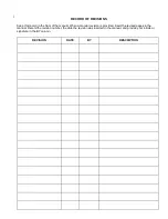
New Machine Pre-Operation Inspection
3


