ESP module
26
ESP module
(Applies to Chairman 2s)
Removal
1.
Raise the seat to it highest position, or to raise
it manually, see page 7.
2.
Turn off the main power switch on the
Control Panel.
3.
Set the main fuse in the “OFF” position, see
page 30.
4.
Remove the housing from the seat lift and
chassis, see page 8.
5.
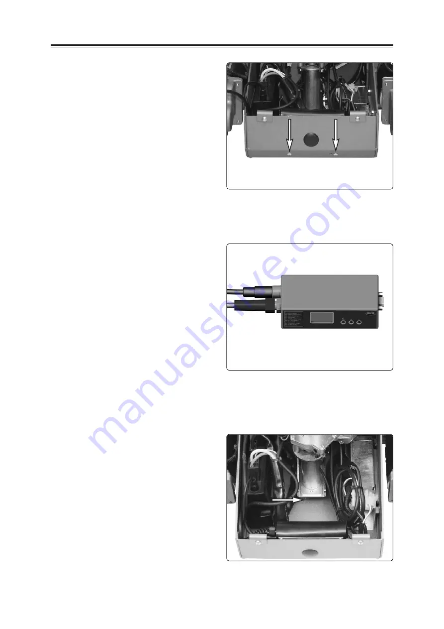
Unscrew and remove the two screws which hold
the ESP module in position, see fig. 56.
6.
Remove the ESP module connecting cable
from the Pilot+ controller, drawing it straight
out, see fig. 60:1.
7.
Remove the control panel connection cable
from the ESP module, drawing it straight out,
see fig. 60:2.
Fig. 56. The ESP module is mounted
and attached with two screws to the
front edge of the chassis.
Fig. 57. ESP module.
Fitting
1.
Fit the ESP module connecting cable to the
output connection, see fig 60:1.
2.
Fit the Control Panel connection cable to the
ESP module, see fig. 60:2.
3.
Attach the ESP module in the chassis using
the two screws, see fig. 56.
NB!
Check that the ESP module is firmly in
position and that the screws are screwed in
securely.
4.
Tip down the protective rubber sheet on the
back of the ESP module, see fig. 58.
NB!
Check that no cables cross the area under
the seat lift, near the drive belt of the seat lift,
see fig. 58.
Fig. 58. Keep area beneath seat lift free of cabling.
Summary of Contents for Chairman 2k
Page 1: ...SERVICE MANUAL Chairman 2k 2s US ...
Page 2: ......
Page 32: ...32 Distribution chart A B C D E F 1 2 3 4 ...
Page 33: ...33 Distribution chart Distribution chart A B C D E F 5 6 7 8 ...
Page 37: ......
Page 38: ......
Page 39: ......
Page 40: ...Article no 201158 US 0 ...


