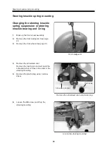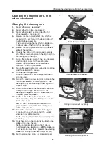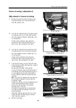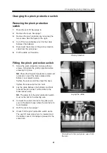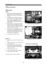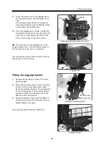
Changing the manual wheel base
38
Changing the manual wheel base
When delivered, the wheelchair is always
transported at its shortest possible length.
When it has been unpacked, it must be adjusted
to the correct length. On wheelchairs which are
equipped with manual extension, the length is
adjusted on the adjustment bar in the rear wheel
assembly. See the figures to the right.
1.
Remove the screw and nut from the
adjustment bar in the rear wheel assembly.
2.
Set the desired distance between the seat
and the foot plate. Choose between seven
different lengths. See the table below.
3.
Screw the adjustment bar in place.
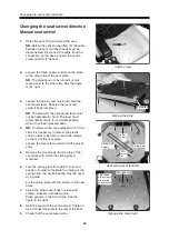
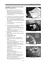
Manual extension
D
C,D
E,F
G
A
B
C
B
A
E
F
G
Chassi
Justerstång
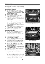
It is possible to set seven different lengths.
When the wheelchair is transported, hole "G" in
the adjustment bar always matches hole "G" in
the chassis, i.e. the shortest length. See the
example to the right. The lengths below indicate
the c-c dimensions between the front and rear
wheels.
Other lengths are:
A to A = 1015 mm
B to B = 980 mm
C to C = 945 mm
D to D = 910 mm
E to E = 885 mm
F to F = 850 mm
G to G = 815 mm
NB.
If the wheel base is mounted in its shortest
position, service in the front wheel assembly will
be made more difficult because the brake
release handle will make it impossible to remove
the foot plate in the normal way. However, it is
possible to remove the foot plate by loosening
the screws of the brake release handle and
folding the handle away. It is then possible to lift
off the foot plate.
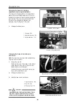
Positions of the adjustment bar
Adjustment bar
Chassis
Summary of Contents for Trax
Page 1: ...SERVICE MANUAL Trax US ...
Page 2: ......
Page 57: ...57 Notes ...
Page 60: ......
Page 61: ......
Page 62: ......
Page 63: ......
Page 64: ...Order no 201096 US 0 ...


