39
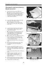
Electric wheel base adjustment
Removal
1.
Move the foot plate in.
If the adjustment device motor for extension
is defective, the adjustment device must be
detached from the front wheel assembly and
the rear wheel assembly. See the figures to
the right.
2.
Remove the protective plate under the front
wheel assembly. See page 32.
3.
Loosen the bolt on the flat bar under the
front wheel assembly.
4.
Raise the seat lift and switch off the power
on the manoeuvring panel and then the main
fuse/battery cut-out.
5.
Remove the cover. See page 7.
6.
Remove the side cover on the electronics
and unscrew and remove the wide contact
(SUB-D) and the charging contact on the
other side of the electronics.
Loosen the three screws on the rear of the
chassis and lift up the electronics. See page 42.
Loosen the mounting plate which holds the
jack panel. It is held by two screws on the
rear of the chassis. See page 43.
7.
Loosen the screw at the rear of the
adjustment device.
8.
Block up the wheelchair under the battery
box so that the wheels are approximately 5
cm clear of the ground.
9.
Detach the bumper mountings on both sides.
NB.
When the wheelchair is blocked up
under the battery box, the lower frame
moves down, which makes it easier to change
the extension motor.
10.
Disconnect the connections on the extension
motor.
11.
Tip the motor so that it is free of the steering
wire and pull it out backwards.
Fitting
Fitting takes place in the reverse order.
1.
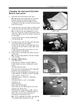
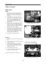
Fit the flat bar on the extension motor. When
the flat bar is pressed into the extension
tube, the bent end must point downwards.
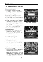
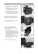
Screw the extension motor in place in the
rearmost hole in the mounting on the rear
wheel assembly.
Screw the flat bar in place in the front wheel
assembly.
2.
Connect the cable to the new adjustment
device motor.
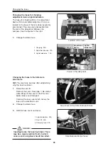
NB.
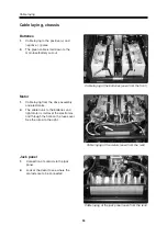
Check that the spring which pulls the
steering wire down is intact.
3.
Fit the bumper mountings.
4.
Refit the electronics and jack panel.
See pages 42-43.
Electric wheel base adjustment
Mounting in front wheel assembly
Mounting in rear wheel assembly
Steering wire with spring
Summary of Contents for Trax
Page 1: ...SERVICE MANUAL Trax US ...
Page 2: ......
Page 57: ...57 Notes ...
Page 60: ......
Page 61: ......
Page 62: ......
Page 63: ......
Page 64: ...Order no 201096 US 0 ...


