Changing the jack panel
47
Removing the jack panel
1.
First switch off the power on the manoeuvring panel
and then switch off the electric circuit with the
battery cut-out.
2.
Remove the cover. See page 7.
3.
Disconnect the connections from the batteries
positive (+) and negative (-) poles.
4.
Cut the cable ties from the interference suppression
cards and unscrew the electronics connections to
the interference suppression card.
5.
Unscrew the three screws which fix the electronics
to the chassis. See the previous page.
6.
Remove the electronics from the chassis. See page 42.
7.
Disconnect all contacts from the jack panel and
release them from the quick-action fasteners.
8.
Unscrew the charging socket from the chassis.
It is held in place by two screws.
NB.
If the chair is
equipped with electrical extension, the contacts must
be disconnected from the adjustment device motor.
9.
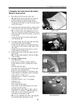
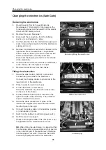
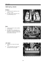
Unscrew the jack panel, which is held in place by
two screws on the rear of the chassis. See the
figure to the right.
10.
Removal is facilitated if the mounting plate on the
jack panel is first unscrewed. It is held in place by
screws underneath.
Changing the jack panel
The jack panel's mounting on the chassis
Jack panel
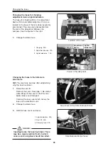
Contacts in the jack panel
Fitting the jack panel
1.
Screw the jack panel in place with two screws.
2.
Screw the charging socket to the chassis. It is fixed
to the chassis with two screws. Do not tighten the
screws too hard.
NB.
If the chair is equipped with
electrical extension, the contacts on the rear of the
jack panel must be connected to the adjustment
device motor of the electrical extension.
3.
Connect all contacts to the jack panel and fix them
in the quick-action fasteners. The contacts are
connected as shown by the decal on the jack panel.
4.
Connect the contacts to the electronics and screw
the SUB-D contact in place. Fit the protective cover
which is located on the right-hand side of the electronics.
Fit the protective cover with one screw.
5.
Place the electronics on the chassis. Connect the
charging cable to the lower left part of the electronics.
6.
Fit the electronics to the chassis. Screw the electronics
in place with three screws. See the previous page.
7.
Screw the electrical connections in place and tie
them to the interference suppression card.
8.
Connect the battery cable to the batteries positive
(+) and negative (-) poles.
9.
Switch on the battery cut-out/main power switch.
10.
Refit the cover. See page 7.
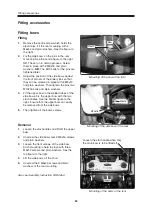
Check that the lights cable of the rear cover is not
caught between the motor/brake and cover.
Summary of Contents for Trax
Page 1: ...SERVICE MANUAL Trax US ...
Page 2: ......
Page 57: ...57 Notes ...
Page 60: ......
Page 61: ......
Page 62: ......
Page 63: ......
Page 64: ...Order no 201096 US 0 ...

