Accessory Installation
Always turn off the air supply and disconnect the air supply hose before installing, removing or adjusting any
accessory on this tool or before performing any maintenance on this tool. Failure to do so could result in an
injury.
1.
Open the retainer.
2. Insert the drill rod into the hammer.
3. Close the retainer.
• Do not repair the tool at the work site. Always take the tool to a repair shop. Never drag the tool on the ground.
The air port and other openings will become clogged with dirt and debris.
• Compressed air is dangerous. Avoid pointing the hose at any of your co-workers or yourself and never use the
air to clear the worksite or work clothing.
• Do not operate the tool unless the drill steel is pushed against the worked material to avoid premature wear of
parts and reduce the vibration isolation properties of the tool.
The starting lever has 4 positions:
1/ The starting lever is perpendicular to the hammer axis – STOP
2/ The starting lever is 45 degrees forwards – SLOW DRILLING
3/ The starting lever is forwards parallel with the hammer axis – FULL DRILLING OUTPUT
4/ The starting lever is backwards – FLUSHING THE HOLE
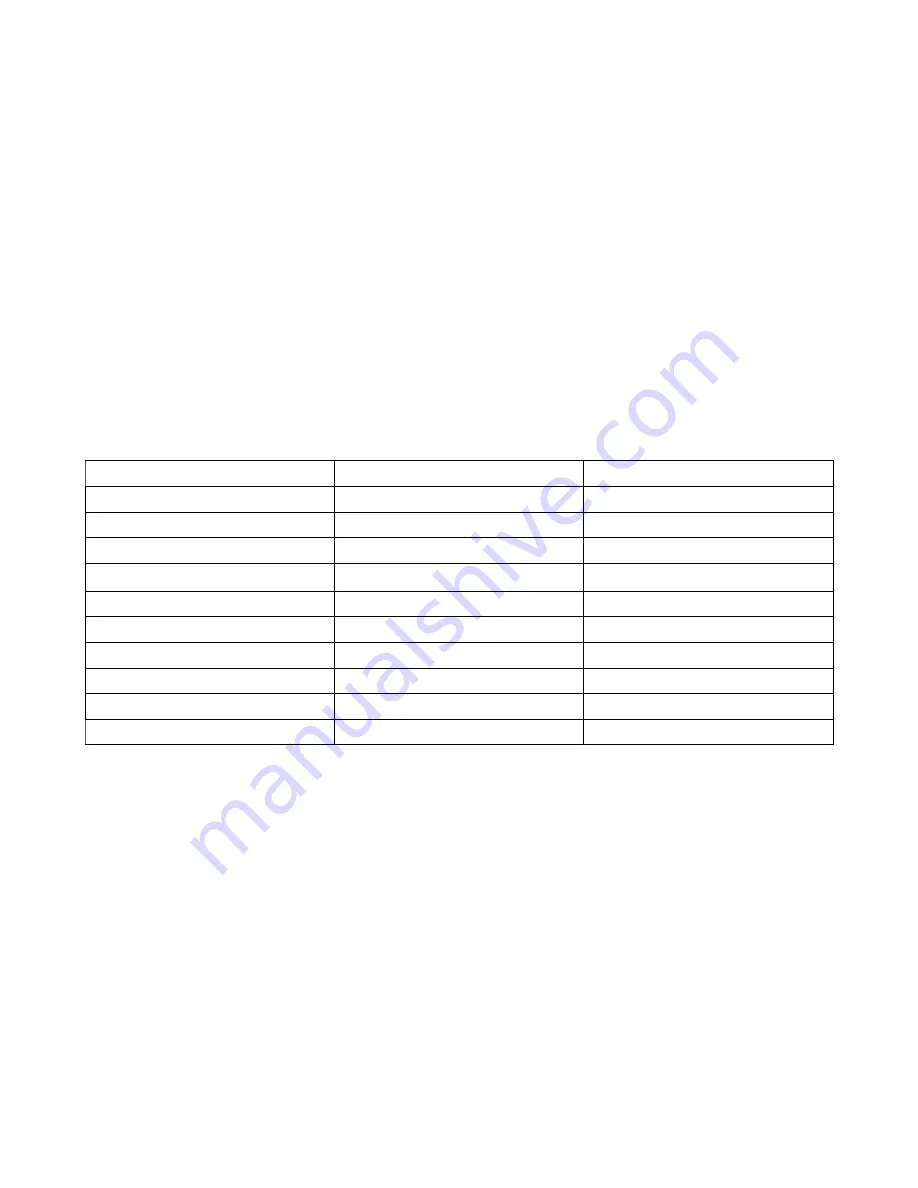
SPECIFICATIONS
Weight
kg
26,5
Length
mm
720
Height
mm
285
Working Pressure
bar
4 – 6
Air Consumption
m
3
/min
4
Impacts per Revolution
–
16
Impact rate
1/min
2100
Chuck Size
mm
hex. 22X108
Air Supply Hose
mm
25
Water Supply Hose
mm
13
Torque
Nm
16
DISASSEMBLING THE VK23 ROCK DRILL
GENERAL INSTRUCTIONS
• Clean the outer surface of the rock drill.
• Do not disassemble the rock drill any further than necessary to replace or repair damaged or worn parts.
• Whenever grasping the rock drill in a vice, always use leather or copper covered vice jaws to protect the
surface of the part and help to prevent distortion. Take extra care with threaded parts and housings.
• Do not remove any part that is a press fit in or on a subassembly unless the removal of the part is necessary
for repairs or replacement.
• Do not disassemble the rock drill unless a complete set of seals and o-rings is available for replacement.
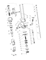
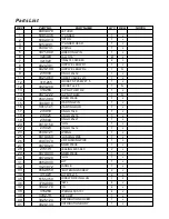
All components are hold together by 2 side bolts (33). Screw out the nuts (34), remove side bolts (33) and
handle (32).
Remove the cylinder cover (51) step by step with the stirrup (52) and drill bushing (49), impact sleeve (46),
piston (2) with the tang nut (44), cylinder (1) with the pin (60), bottom distribution cover (42) with the stop (47),
distribution body (41), upper distribution cover (40), distribution ring (43), ratchet (39) with the screw driving lug
(35), pawls (36), pins (37) and springs (38).
Warning! The threads of the tang nut (44) and the carrier (50) are left-handed!
Summary of Contents for VK 23
Page 6: ......


