background image

3.i - INSTALLATIONEN MIT BUS-VERBINDUNGEN

Durch die BUS-Verbindung kann die Anwesenheit von Gas an mehreren Orten
gleichzeitig durch Aktivierung des Elektroventils erhoben werden, wobei lokale
und zentralisierte Warnmeldungen erscheinen.

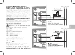
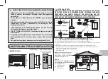
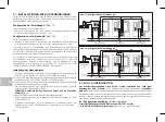
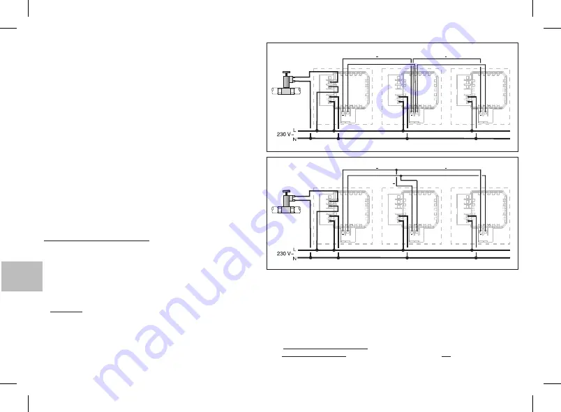
Konfiguration der Verbindung A

(Abb. 17)

• Eine Haupteinheit mit Gasabsperrventil
• Maximal 14 Untereinheiten, die über eine max. 1 km lange, zweidrähtige Leitung

an die Haupteinheit angeschlossen sind 1.5 mm².

Konfiguration der Verbindung B

(Abb. 18)

• Eine Haupteinheit mit Gasabsperrventil
• Maximal 10 Untereinheiten, Anschluß an die Haupteinheit über zweidrähtige

Leitungen mit einer Länge von max. 100 m und Leitungsquerschnitt 1,5 mm².

Es gibt zwei Typen von Untereinheiten: reine Anzeige-Einheiten mit akustischen
und optischen Alarmmeldungen und lokalem Alarmspeicher oder aktive Einheiten,
die mit einem Relais und lokalem Alarmspeicher ausgerüstet sind und ebenfalls
akustische und optische Warnmeldungen auslösen.

Die Leitung ist vor Kurzschlüssen und Verwechslung von Drähten geschützt (die
Kommunikation wird zwar unterbrochen, doch bleiben die an den BUS
angeschlossenen Detektoren unbeschädigt). Eine Selbstdiagnose erhebt
Anschlußfehler und Störungen bei dem BUS und zeigt diese an (siehe
“BEDIENUNGSANLEITUNG FÜR ANWENDER”, Abschnitt 6.u).

Installation der Gasdetektoren

• Sämtliche Gasdetektoren sind unter Berücksichtigung der Anweisungen zu

installieren, die im Abschnitt 1.i - INSTALLATION aufgeführt werden.

• Der Anschluß der Haupteinheit an die Netzspannung und das Elektroventil wird

gemäß Abschnitt 2.i - ELEKTRISCHE ANSCHLÜSSE ausgeführt.

• Der Anschluß weiterer Detektoren an die Netzspannung wird in der betreffenden

technischen Dokumentation beschrieben.

• Alle Gasdetektoren durch die Klemmen

( ) und

( ), wie in Abb. 17 und 18

6 -

7 +

gezeigt, an die BUS-Leitung anschließen.

: Achten Sie bei dem Anschluß darauf, daß die Polaritäten

VORSICHT
stimmen (- e +)

.

• Sämtliche Detektoren ausschalten und Netzspannung anlegen.
• BUS-Leitung konfigurieren, wie in folgendem Abschnitt beschrieben (4.i BUS-

KONFIGURATION).

• Probelauf durchführen, um die einwandfreie Funktionstüchtigkeit der

Detektoren und des BUS-Schaltkreises zu überprüfen, wie in Abschnitt 5.i -
TEST beschrieben.

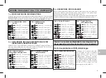
4.i - BUS - KONFIGURATION

Das Konfigurationsverfahren muss bei der ersten Installation und nach jeder
Änderung der BUS - Struktur

ausgeführt

(z. B. Einfügen eines neuen Gasdetektors)

werden

. Die über die BUS - Leitung verbundenen dezentralen Gasdetektoren müssen von der

Haupteinheit erkannt werden. Die Einheiten der Bus-Leitung, die außer der Haupteinheit über
ein Relais verfügen, werden automatisch als dezentrale Einheit konfiguriert. Die Zuweisung der
Funktion als Haupteinheit kann geändert werden.

A) - Konfigurationsverfahren

(Erstkonfiguration)

Alle

und Wahlschalter ON-TEST auf

Geräte spannungslos

ON

:

(grüne LED ein - gelbe LEB blinkt)

Alle Geräte mit Spannung versorgen

7

6

+

7

6

+

7

6

+

+

+

BUS

Elektroventil

NO

1

1

1

2

2

2

3

BUS

4

5

Haupteinheit

Untereinheit

Untereinheit

7

6

+

7

6

+

7

6

+

+

+

BUS

Elektroventil

NO

1

1

1

2

2

2

3

BUS

4

5

Haupteinheit

Untereinheit

Untereinheit

BUS

Abb. 17 -

A

Konfiguration der Verbindung

Abb. 18 -

B

Konfiguration der Verbindung

40

+

DE

Summary of Contents for 1GA47917GPL/P

Page 1: ...ne installation mit optionaler Halterung Mit Relais zur Ansteuerung des Elektroventils zur Einzelanwendung oder als Haupteinheit die ber BUS Verbindungen mit anderen Detektoren verbunden wird DETECTOR...

Page 2: ...age 15 Page 17 DESCRIPTION ENTRETIEN AVERTISSEMENTS CARACTERISTIQUES TECHNIQUES SIGNALISATIONS ET COMMANDES PRINCIPALES MODE D EMPLOI POUR L UTILISATEUR INSTRUCTIONS POUR L INSTALLATION Page 23 Page 2...

Page 3: ...n quanto fornisce importanti indicazioni riguardanti la sicurezza l uso e la manutenzione Conservare con cura il libretto istruzioni per successive consultazioni L installazione ed il collegamento ele...

Page 4: ...T Selettore ON TEST Fig 1 Tempo riscaldamento sensore Legenda segnalazioni luminose e acustiche acceso fisso intermittente spento LED BUZZER Tensione di alimentazione Rel per comando elettrovalvola Po...

Page 5: ...e bassa concentrazione di gas 3 u SEGNALAZIONE PRESENZA DI GAS E ALLARME GAS Se la concentrazione di gas nell ambiente supera il valore limite d intervento l apparecchio segnala tale situazione accend...

Page 6: ...L apparecchio segnala automaticamente la scadenza per la sostituzione prevista dalle norme dopo 5 anni di funzionamento facendo lampeggiare contemporaneamente LED verde LED giallo e LED rosso 1 ed eme...

Page 7: ...E BUS BUS Installare il rivelatore per Metano a 30 cm max dal soffitto Installare il rivelatore per GPL a 30 cm max dal piano pavimento Installare i rivelatori da 1 m a 4 m dagli apparecchi a gas Non...

Page 8: ...sportare diaframma 7 I Installazione a SEMINCASSO Installazione a PARETE Supporto per installazione a semincasso in opzione acquistabile separatamente Base per installazione a parete B A A A D C D B A...

Page 9: ...morsetti n 6 n 7 BUS Fig 16a Esempio collegamento a elettrovalvola normalmente chiusa Fig 16b Esempio collegamento a elettrovalvola normalmente aperta a riarmo manuale 230V 50 60 Hz Elettrovalvola NA...

Page 10: ...azione di rete ed all elettrovalvola come indicato nel capitolo 2 i COLLEGAMENTI ELETTRICI Collegare i rivelatori remoti all alimentazione di rete come indicato nella specifica documentazione tecnica...

Page 11: ...ento Entro 5 minuti sulla VECCHIA UNIT PRINCIPALE Spostare il selettore su quindi premere brevemente il tasto ON TEST ON RESET I LED rossi sono spenti l unit assegnata alla nuova unit principale che e...

Page 12: ...e 10 ed applicarla all apparecchio Staccare l etichetta corrispondente all anno di sostituzione dell apparecchio ed applicarla es Anno d installazione 2015 5 anni applicare l etichetta 2020 Registrare...

Page 13: ...t provides important information regarding safety use and maintenance Keep the booklet in a safe place for future reference The installation and electrical connection of gas detectors and appliances m...

Page 14: ...units 1 km with 2 wires of 1 5 mm section 2 LVD EN 50194 CEI 216 8 semi flush mounted EMC EN 50270 PRINCIPAL SIGNALS AND CONTROLS PERFORMANCE FEATURES Performance both models Alarm memory Clear alarm...

Page 15: ...u INDICATION OF GAS WARNING AND GAS ALARM WARNING gas can be smelt in the environment before the appliance signals alarm Where several units are BUS connected peripheral units in gas alarm level stat...

Page 16: ...ning after 5 years of operation The appliance automatically warns when it is time for replacement in accordance with regulations after 5 years of operation the green LED yellow LED and red LED 1 will...

Page 17: ...OF GAS POWERED EQUIPMENT ARE TO BE RESPECTED AS ARE STANDARDS COVERING SMOKE DISPERSION AND VENTILATION OF ENCLOSED AREAS EVEN THOUGH GAS DETECTIONEQUIPMENT ISINSTALLED min 1 m max 4 m Natural gas det...

Page 18: ...ase Fig 13 Fig 14 SEMI FLUSH mounting SURFACE mounting Base for surface mounting A Holes for fixing the support on round or rectangular flush mounted box the base surface mounted on round or rectangul...

Page 19: ...suring omnipolar disconnection For the connection of several appliances to a BUS line see the next chapter n 6 n 7 BUS For the electrical connections attach the detector terminals using cables of cros...

Page 20: ...he main unit to the power supply and to the solenoid valve as explained in chapter 2 i ELECTRICAL CONNECTIONS Connect the remote detectors to the power supply as explained in the relative technical do...

Page 21: ...N UNIT Move the selector to then briefly press the key The red ON TEST ON RESET LEDs are off the unit is assigned to the new main unit which emits a confirming beep ON EVERY OTHER REMOTE UNIT Briefly...

Page 22: ...fix it to the appliance Select the label corresponding to the year of replacement e g Year of installation 2015 5 years fix the label 2020 remove from the backing sheet and fix Record the date of ins...

Page 23: ...urit l utilisation et l entretien Conserver soigneusement le livret d instructions pour pouvoir le consulter par la suite L installation et la connexion lectrique des d tecteurs de gaz et des appareil...

Page 24: ...94 CEI 216 8 montage semi encastr EMC EN 50270 SIGNALISATIONS ET COMMANDES PRINCIPAUX CARACT RISTIQUES DES PRESTATIONS Prestations pour les deux mod les M moire de l alarme d clench e Effacement de la...

Page 25: ...e concentration de gaz 3 u SIGNALISATION DE PR SENCE DE GAZ ET ALARME GAZ ATTENTION il est possible que dans l air on per oit de l odeur de gaz avant que l appareil donne l alarme Sur les installation...

Page 26: ...appareil signale automatiquement les d lais pr vus par les normes pour le remplacement apr s 5 ans de fonctionnement Pour ce faire il fait clignoter en m me temps le VOYANT verte le VOYANT jaune et le...

Page 27: ...AUXDOIVENT TRE RESPECT ES min 1 m max 4 m D tecteur de gaz naturel Fig 11 min 1 m max 4 m D tecteur de gaz butane propane Installer le d tecteur de gaz naturel 30 cm max du plafond Installer le d tect...

Page 28: ...de la goulotte murale enlever la membrane 7 I B A A A D C D B A A A A A E Pour un montage correct du detecteurs de gaz sur la plaque ou la base murale celles ci ne doivent pas tre courb es cause d un...

Page 29: ...imum de 1 5 mm 2 Fig 16a Example branchement l lectrovanne normalement ferm Fig 16b Example branchement l lectrovanne normalement ouverte r tablissement manuel 230V 50 60 Hz Electrovanne NO r tablisse...

Page 30: ...ncipale l alimentation r seau et l lectrovanne comme indiqu dans le chapitre 2 i BRANCHEMENTS LECTRIQUES Brancher les d tecteurs distants l alimentation r seau comme indiqu dans la documentation techn...

Page 31: ...nutes sur la VIEILLE UNIT PRINCIPALE d placer le s lecteur sur et appuyer bri vement le bouton ON TEST ON Les leds rouges sont teintes l unit est affect e la nouvelle unit RESET principale qui met un...

Page 32: ...vus report s ci contre les dates de installation fabrication remplacement local d installation cachet et signature de l installateur 6 i ENREGISTREMENT DES DATES DE REMPLACEMENT DE L APPAREIL 07 2020...

Page 33: ...Sicherheit Gebrauch und Wartung Bewahren Sie die Gebrauchsanleitung f r sp teres Nachschlagen sorgf ltig auf Die Installation und der elektrische Anschluss der Gasdetektoren und Ger te muss durch qual...

Page 34: ...Dr hte Querschnitt 1 5 mm LVD EN 50194 CEI 216 8 Eingelassene Installation EMC EN 50270 MELDUNGEN UND HAUPTBEFEHLE LEISTUNGSMERKMALE Leistungen beider Modelle Speicher Alarmberichte L schung des Alarm...

Page 35: ...alanzeige niedrige Gaskonzentration 3 u GASANZEIGE UND GASALARM Wenn die Gaskonzentration im Raum die Ansprechschwelle berschreitet meldet das Ger t diese Situation durch Aufleuchten der roten Alarmle...

Page 36: ...odischen Anzeige der Ersetzung des Ger tes Das Ger t meldet automatisch die von den Normenvorschriften vorgesehene F lligkeit zwecks Ersatz nach mehr als 5 j hrigem Betrieb durch das gleichzeitige Bli...

Page 37: ...stallieren Methan max 30 cm von der Raumdecke Detektor f r installieren Fl ssiggas mindestens 30 cm ber dem Fu boden Alle Detektoren in einem Abstand von 1 4 m von Gasger ten installieren Die Gasdetek...

Page 38: ...elkanal zur Wand Blende ausbrechen 7 I B A A A D C D B A A A A A E F r die korrekte Montage der Gasdetektoren auf der Halterung oder der Wandbasis d rfen sich dieselben nicht durch zu starkes Festzieh...

Page 39: ...rweise geschlossenem Elektroventil Abb 16b Beispiele Verbindung mit normalerweise offenem Elektroventil Manuel zu r sten 230V 50 60 Hz Elektroventil NO Manuel zu r sten 230V 50 60 Hz 39 Der Gasdetekto...

Page 40: ...er Haupteinheit an die Netzspannung und das Elektroventil wird gem Abschnitt 2 i ELEKTRISCHE ANSCHL SSE ausgef hrt Der Anschlu weiterer Detektoren an die Netzspannung wird in der betreffenden technisc...

Page 41: ...hlie end kurz die Taste ON TEST ON RESET dr cken die roten LEDs sind ausgeschaltet die Einheit ist der neuen Haupteinheit zugeordnet die mit einem kurzen akustischen Signal best tigt AUF JEDER WEITERE...

Page 42: ...5 5 Jahre Etikett 2020 anbringen In den betreffenden Feldern wie unten angegeben Installations bzw Erstellungsdatum Ersatzdatum Installations Raum Unterschrift und Stempel des Installateurs 6 i DOKUME...

Page 43: ...utilizar el producto Proporciona importantes indicaciones de seguridad uso y mantenimiento Guarde el manual de instrucciones para futuras consultas La instalaci n y conexi n el ctrica de los detector...

Page 44: ...1 5 mm de secci n 2 LVD EN 50194 CEI 216 8 instalaci n semiempotrada EMC EN 50270 SE ALIZACIONES Y COMANDOS PRINCIPALES PRESTACIONES Prestaciones para ambos modelos Memoria de alarma disparada Cancela...

Page 45: ...as 3 u SE ALIZACI N PRESENCIA DE GAS Y ALARMA DE GAS Si la concentraci n de gas en el ambiente supera el valor l mite de la detecci n el aparato para indicar esta situaci n enciende la luz roja 1 de l...

Page 46: ...uci n del aparato El aparato se ala autom ticamente el t rmino del plazo para la sustituci n previsto por las normas despu s de 5 a os de funcionamiento haciendo parpadear simult neamente el LED verde...

Page 47: ...a m xima de 30 cm del cielorraso para detectar Metano Para detectar el aparato debe estar a una GPL distancia m xima de 30 cm del piso Instalar el detector de 1 a 4 metros de los artefactos a gas No i...

Page 48: ...red quitar el diafragma 7 B A A A D C D B A A A A A E Para asegurar un correcto montaje del detectores de gas en el soporte o en la base de pared estos no deben presentar curvaturas debidas al apriete...

Page 49: ...rminal cables con secci n m xima de 1 5 mm2 IMPORTANTE la instalaci n y la conexi n el ctrica de dispositivos y aparatos deben ser realizadas por personal cualificado y en conformidad con la normativa...

Page 50: ...principal a la red de alimentaci n y a la electrov lvula como se indica en el cap tulo 2 i CONEXIONES EL CTRICAS Conectar los detectores remotos a la red de alimentaci n como se indica en la documenta...

Page 51: ...D PRINCIPAL poner el selector en y luego pulsar durante algunos segundos la ON TEST ON tecla Los LEDS rojos se apagan y la unidad remota se asigna a la unidad RESET principal que emite una breve se al...

Page 52: ...s que se indican de a lado las fechas de instalaci n fabricaci n sustituci n lugar de instalaci n sello y firma del instalador 6 i REGISTRO DE FECHAS DE SUSTITUCI N DEL APARATO Fecha de instalaci n Lu...

Page 53: ...53 NOTE NOTES ANMERKUNGEN NOTAS...

Page 54: ...xample sales points in case you buy a new and similar product local collection points waste collection centre local recycling center etc By ensuring this product is disposed of correctly you will help...

Page 55: ...en Sie von Ihrem Gemeinde den kommunalen Entsorgungsbetrieben oder dem Gesch ft in dem Sie das Produkt gekauft haben DE TRATAMIENTO DE LOS APARATOS EL CTRICOS Y ELECTR NICOS EN FINAL DE VIDA Ese s mbo...

Page 56: ...ion Der Hersteller beh lt sich das Recht vor notwendige technische nderungen ohne Vorank ndigung vorzunehmen Il costruttore si riserva la facolt di introdurre tutte le modifiche tecniche e costruttive...

Reviews: