background image

Pagina 24 di 53

46

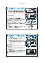
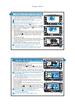
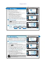
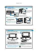
Pour les opérations de couplage des chronothermostats "Master" aux zones (canaux),
s'en tenir scrupuleusement aux indications du chapitre "Prédisposition du récepteur
pour le fonctionnement avec "Master" du manuel d'instructions des récepteurs.

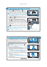
SUR LE CHRONOTHERMOSTAT "MASTER", activer l'état de "Master Test":

appuyer sur la

l'inscription “

” s'affichera sur l'écran (exemple sur la fig. 82).

touche Master pendant 4 secondes

MASt

SUR LE RÉCEPTEUR:

vérifier l'état de la zone et effectuer toutes les opérations de couplage indiquées sur le manuel d'instructions du récepteur.

Une fois les opérations terminées:

SUR LE CHRONOTHERMOSTAT “MASTER”

désactiver l'état de “Master - Test” appuyer sur la

:

touche Master pendant 1 seconde

l'inscription “

” disparaît et le programme précédemment en cours s'affiche sur l'écran.

MASt

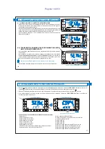
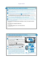
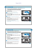
9.3.2) ANNULATION DU COUPLAGE D'UNE ZONE À UN “MASTER”

Pour les opérations d'annulation s'en tenir également scrupuleusement aux indications du manuel d'instructions des récepteurs.

.

SUR LE CHRONOTHERMOSTAT "MASTER", activer l'état de "Master Test":

appuyer sur la

l'inscription “

” s'affichera sur l'écran (exemple sur la fig. 82).

touche Master pendant 4 secondes

MASt

.

SUR LE RÉCEPTEUR:

vérifier l'état de la zone et effectuer toutes les opérations d’annulation indiquées sur le manuel d'instructions du récepteur.

SUR LE CHRONOTHERMOSTAT "MASTER", désactiver l'état de "Master Test":

appuyer sur la

: l'inscription “

” disparaît et le programme précédemment en cours s'affiche sur

touche Master pendant 1 seconde

MASt

l'écran.

9.3.1) COUPLAGE DES ZONES AUX “MASTER”

(à effectuer après avoir réalisé les opérations de couplage des
transmetteurs, voir par ex. le paragraphe 4.8)

INSTRUCTIONS POUR L'INSTALLATEUR

Cette fonction peut être protégée par un mot de passe (voir chapitre ).

8

L'état de “Master - Test” reste activé pendant 3 minutes maximum ; après quoi le chronothermostat retournera à son fonctionnement
normal.

9 - FONCTION “MASTER”

0

8

10 12 14 16 18

2

4

6

t1
t2
t3

20 22

fig. 82

appuyer pendant 4 secondes

FR

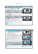
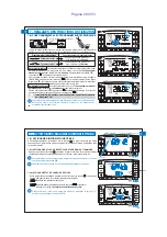
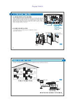
Dans les installations avec présence de zones couplées à un chronothermostat
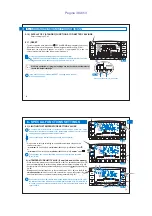
"MASTER", la fonction "Master" peut être activée ou désactivée par l'utilisateur en
appuyant brièvement sur la touche

.

Master

L'état de "Master" activé est indiqué sur l'écran par l'inscription

allumée

Master

fixement (fig. 83).

Fonction “Master” désactivée

: le chronothermostat “MASTER” se comporte comme un chronothermostat normal et il agit seulement sur la

zone avec laquelle il est couplé.

Fonction “Master” activée

: le chronothermostat “MASTER” remplace, jusqu'à la désactivation de la fonction, les chronothermostats et/ou

thermostats couplés aux zones assignées, aux modalités indiquées dans les paragraphes successifs.
En FONCTIONNEMENT "MASTER", il est possible de modifier les niveaux et les valeurs de température, de passer de manuel
temporaire à manuel permanent ou à programme (de profil) en fonction.

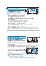
9.4.1)

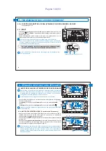
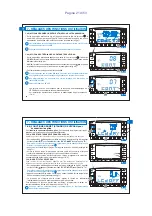
MASTER MANUEL TEMPORAIRE

Activation

:

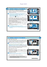
sur le chronothermostat MASTER appuyer brièvement sur la touche “

” pour

entrer en fonctionnement manuel temporaire; sur l'écran le symbole “

clignotant (voir plus de détails au paragraphe

) (exemple sur la fig. 84).

7.1 point A

Appuyer brièvement sur la touche “

”: l'inscription

s'allume

Master

Master

fixement.

Fonctionnement:

la thermorégulation de toutes les zones couplées au “Master” est gérée par le

"Master"; niveau de température (confort “t1”, économie “t2”, absence “t3”) et les
valeurs de température sont celles programmées dans le “Master”.

9.4) MODALITÉ DE FONCTIONNEMENT “MASTER”

INSTRUCTIONS D'UTILISATION POUR L'UTILISATEUR

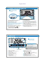
En fonctionnement “Master manuel temporaire” à minuit

il est possible de constater les cas suivants:

• Si la fonction “Master est activée avec chronothermostat en mode “manuel temporaire”, la fonction “manuel temporaire” et
“Master” cessent; le chronothermostat se place en mode programme.
• Si la fonction “Master a été activée avant de placer le chronothermostat en mode “manuel temporaire”, la fonction “manuel
temporaire” cesse et le chronothermostat se place en mode “Master de programme”

.

(voir fonctionnement au par.

9.4.3)

47

Exemple : fonctionnement avec

Master manuel temporaire

9 - FONCTION “MASTER”

fig. 84

0

8

10 12 14 16 18

2

4

6

20 22

t1
t2
t3

.

.

.

fig. 83

0

8

10 12 14 16 18

2

4

6

20 22

t1
t2
t3

.

.

.

FR

Summary of Contents for 1TXCRTX05

Page 1: ...iption Data Date Firma Sign Modifiche Modify Codice distinta base L Tettamanzi A Aggiornamento Banda di frequenza e Dichiarazione conformit UE semplificata 30 08 17 L Tettamanzi FI307 UNI EN ISO 9001...

Page 2: ...programmer librement 2 hivers dont un pr d fini 1 t sont d j configur s dans sa m moire permanente et ont t tudi s pour offrir un confort maximum il suffit de quelques secondes seulement pour choisir...

Page 3: ...entent aucun risque pour la sant des personnes et des animaux Important le fabricant se r serve le droit d introduire toutes les modifications techniques et de fabrication qu il retiendra n cessaires...

Page 4: ...lone chronothermostat de la m me s rie Des fonctions particuli res suppl mentaires des touches sont d crites dans les paragraphes sp cifiques d utilisation Combinaison des touches pour la commande Res...

Page 5: ...tion li es aux mat riaux qui ont un impact sur la port e dans l Air libre d clar e ci dessus Avec l aide de la fonction voir paragraphe 4 9 il est test possible de v rifier pr alablement la position o...

Page 6: ...sp cifique des piles fig B Ins rer ou remplacer par 2 piles de 1 5 V type AA LR6 en faisant attention la polarit fig B Attention les piles peuvent avoir une dur e de vie sup rieure trois ans Nous vous...

Page 7: ...appuyer pendant 1 seconde fig C fig D 0 8 10 12 14 16 18 20 22 2 4 6 t1 t2 t3 t1 t2 t3 0 8 10 12 14 16 18 20 22 2 4 6 FR 4 INSTALLATION 4 9 TEST DE V RIFICATION DE L INTENSIT DU SIGNAL RADIO SUR LE C...

Page 8: ...t3 fig 2 0 8 10 12 14 16 18 20 22 t1 2 4 6 t2 t3 fig 3 FR 5 1 d PROGRAMMATION HEURE MINUTES en cours 5 1 e CHOIX DU PROGRAMME HEBDOMADAIRE DE FONCTIONNEMENT Apr s avoir configur le jour l heure et le...

Page 9: ...0 22 0 8 1 0 12 14 16 18 20 22 t1 2 4 6 t2 t3 Digit conomie absence confort fig 7 0 8 10 12 14 16 18 2 4 6 t1 t2 t3 20 22 ou appuyer dessus l une des deux touches pendant au moins 4 secondes FR Progra...

Page 10: ...8 10 12 14 16 18 20 22 t1 2 4 6 t2 t3 appuyer pendant 4 secondes 5 PROGRAMMATION DU CHRONOTHERMOSTAT FR Pour modifier les du programme ou r glages pr c demment enregistr s P01 P02 P03 PROG appuyer sur...

Page 11: ...qui satisfont les conditions suivantes t1 sup rieure ou gale t2 sup rieure ou gale t3 t3 sup rieure ou gale t2 sup rieure ou gale t1 Modifier sous 8 secondes la temp rature s lectionn e en utilisant...

Page 12: ...au r glage du jour Une fois l heure en cours configur e appuyer sur la touche pour confirmer OK Le chronothermostat revient au fonctionnement en cours appuyer pendant 4 secondes Exemple de passage d...

Page 13: ...on s lectionne une touche ou correspondant un set de temp rature t1 t2 bloqu le symbole ou la valeur correspondant c t et les digits au t1 t2 centre clignotent exemple sur la fig 3 Dans ce cas il est...

Page 14: ...ppuyer simultan ment appuyer simultan ment 4 secondes fig 33 0 8 10 12 14 16 18 2 4 6 t1 t2 t3 20 22 FR 6 R GLAGES DES FONCTIONS SP CIALES 27 Sur le chronothermostat en r ception appuyer sur la touche...

Page 15: ...4 secondes fig 37 0 8 10 12 14 16 18 2 4 6 t1 t2 t3 20 22 SET configur e 20 C en modalit HIVER Diff rentiel configur 0 3 Exemple C Off On On Appareil en fonctionnement Temps 20 19 7 Appareil en fonct...

Page 16: ...6 t1 t2 t3 20 22 fig 41 0 8 10 12 14 16 18 2 4 6 t1 t2 t3 20 22 appuyer pendant 4 secondes FR 31 7 R GLAGES DES FONCTIONS D UTILISATION 7 1 FONCTIONNEMENT MANUEL 2 modalit s de fonctionnement manuel p...

Page 17: ...2 14 16 18 2 4 6 t1 t2 t3 20 22 fig 48 0 8 10 12 14 16 18 2 4 6 t1 t2 t3 20 22 appuyer pendant 4 secondes FR 33 7 R GLAGES DES FONCTIONS D UTILISATION s lectionner le programme vacances P 04 HOLIDAY A...

Page 18: ...fonctionnera nouveau selon le programme utilis avant la configuration du programme P 04 HOLIDAY fig 58 Date et ou heure de OUT successives celles en cours En appuyant sur la touche exemple en fig 56 l...

Page 19: ...ctualis e toutes les 30 minutes seulement Dans ce cas si les piles sont d charg es l cran affichera le symbole Pour activer la fonction maintenir la touche appuy e environ 6 sec jusqu ce que l inscrip...

Page 20: ...L cran affiche le symbole clignotant et fixe indiquant le for age Pour revenir au fonctionnement programm appuyer sur la touche 0 8 10 12 14 16 18 2 4 6 20 22 t1 t2 t3 0 8 10 12 14 16 18 2 4 6 20 22...

Page 21: ...0 8 10 12 14 16 18 2 4 6 t1 t2 t3 20 22 DAY fig 70 0 8 10 12 14 16 18 2 4 6 t1 t2 t3 20 22 Pour il est possible de programmer l arr t r duire la consommation des piles standby de l cran suivant deux m...

Page 22: ...3 secondes 8 MOT DE PASSE FR 8 1 c MODIFICATION DU MOT DE PASSE Pour modifier le mot de passe proc der comme indiqu ci dessous partir du fonctionnement normal du chronothermostat appuyer environ 3 se...

Page 23: ...0 12 14 16 18 2 4 6 t1 t2 t3 20 22 Master activ TOUCHE MASTER allum e sortie tat de MASTER TEST activation d sactivation fonction Master Zona 1 Zona 2 RESET ON ON Chronothermostat zone 1 Master Chrono...

Page 24: ...s les installations avec pr sence de zones coupl es un chronothermostat MASTER la fonction Master peut tre activ e ou d sactiv e par l utilisateur en appuyant bri vement sur la touche Master L tat de...

Page 25: ...de programme appuyer bri vement sur la touche l inscription s allume fixement Master Master sur l cran Fonctionnement durant les p riodes o le programme profil pr sente des niveaux de temp rature cono...

Page 26: ...upl es au chronothermostat seront thermor gul es sur le niveau du Master en manuel permanent t3 absence Dans toutes les conditions de fonctionnement avec niveau temp rature t3 d absence d crites ci de...

Page 27: ...nd vice versa 3 various freely programmable programs are already set in its permanent memory 2 winter one of which is pre set 1 summer designed to provide maximum comfort Only a few seconds are needed...

Page 28: ...ts packaging Packaging components any plastic bags PVC suspensions etc must be kept out of reach of children Carefully read the instruction manual before using the product as it provides important gui...

Page 29: ...contrast and display standby setting 15 Key for sending transmission Test key for transferring the entire programming to another Clone 16 chronothermostat of the same series 1 2 3 4 5 6 7 8 9 10 11 1...

Page 30: ...via radio For this reason during installation always take into account some necessary precautions to avoiding limiting or in some cases inhibiting radio wave range namely install the device away from...

Page 31: ...en slide again to reveal the second row of keys access to the battery compartment fig B Insert or replace with N 2 X 1 5V batteries type AA LR6 ensuring to place the poles correctly fig B Attention ba...

Page 32: ...nd fig C fig D 0 8 10 12 14 16 18 20 22 2 4 6 t1 t2 t3 t1 t2 t3 0 8 10 12 14 16 18 20 22 2 4 6 62 EN 4 INSTALLATION 4 9 RADIO SIGNAL INTENSITY VERIFICATION TEST This function can be protected by a pas...

Page 33: ...2 14 16 18 20 22 t1 2 4 6 t2 t3 fig 2 0 8 10 12 14 16 18 20 22 t1 2 4 6 t2 t3 fig 3 64 EN 5 1 d PROGRAMMING HOUR MINUTES current 5 1 e SELECTING THE WEEKLY PROGRAM After having set the day the hour an...

Page 34: ...0 12 14 16 18 20 22 t1 2 4 6 t2 t3 Digit economy absence comfort press one of the two keys for at least 4 seconds fig 7 0 8 10 12 14 16 18 2 4 6 t1 t2 t3 20 22 or 66 EN Setting the temperatures for M...

Page 35: ...t1 t2 t3 t1 t2 t3 1 2 3 0 8 10 12 14 16 18 20 22 t1 2 4 6 t2 t3 fig 12 fig 13 0 8 10 12 14 16 18 20 22 t1 2 4 6 t2 t3 68 EN 5 CHRONOTHERMOSTAT PROGRAMMING To change the previously saved settings of p...

Page 36: ...t3 20 22 70 EN 5 CHRONOTHERMOSTAT PROGRAMMING 5 6 CHANGING THE TEMPERATURE SETTINGS COMFORT t1 ECONOMY t2 AND ABSENCE t3 The chronothermostat will accept temperature values that satisfy the follo win...

Page 37: ...urn to day setting Once the current hour is set press to confirm OK The chronothermostat returns to the current program fig 23 0 8 10 12 14 16 18 2 4 6 t1 t2 t3 20 22 fig 22 0 8 10 12 14 16 18 2 4 6 t...

Page 38: ...um t2 Summer Comfort and or Economy in mode If you select a key or relative to a blocked temperature the symbol or t1 t2 t1 t2 the relative value to the side and the central digits ex mple fig 32 will...

Page 39: ...imultaneously press simultaneously for 4 seconds fig 33 0 8 10 12 14 16 18 2 4 6 t1 t2 t3 20 22 76 EN 6 SPECIAL FUNCTIONS SETTINGS On the reception chronothermostat press the key for 4 seconds will ap...

Page 40: ...12 14 16 18 2 4 6 t1 t2 t3 20 22 Time press for 4 seconds fig 37 0 8 10 12 14 16 18 2 4 6 t1 t2 t3 20 22 Device in operation set SET 20 C in WINTER mode Set differential 0 3 Example C Off On On 20 19...

Page 41: ...fig 41 0 8 10 12 14 16 18 2 4 6 t1 t2 t3 20 22 press for 4 seconds 80 EN 7 USER FUNCTIONS SETTINGS 7 1 MANUAL OPERATION There are 2 manual modes while the current program is stopped 7 1 A TEMPORARY M...

Page 42: ...47 0 8 10 12 14 16 18 2 4 6 t1 t2 t3 20 22 fig 48 0 8 10 12 14 16 18 2 4 6 t1 t2 t3 20 22 press for 4 seconds Example absence temperature t3 excluded 82 EN 7 USER FUNCTIONS SETTINGS select the progra...

Page 43: ...the program in operation before program P 04 HOLIDAY insertion OUT date and or time that are later than the current Press example in fig 56 and the chronothermostat will return to the program OK that...

Page 44: ...y consumption to a minimum the temperature displayed on the chronothermostat is only updated every 30 minutes In the event of flat batteries in this condition the below symbol will be enabled on the d...

Page 45: ...blinking symbols and fixed appear on the display to indicate forcing Press on the chronothermostat to return to program operation fig 62 0 8 10 12 14 16 18 2 4 6 20 22 t1 t2 t3 fig 61 0 8 10 12 14 16...

Page 46: ...y in two different ways to reduce battery consumption fig 71 0 8 10 12 14 16 18 2 4 6 t1 t2 t3 20 22 DAY fig 72 0 8 10 12 14 16 18 2 4 6 t1 t2 t3 20 22 DAY fig 70 0 8 10 12 14 16 18 2 4 6 t1 t2 t3 20...

Page 47: ...assword disabled press simultaneously for 3 seconds Correct NO Correct examples 92 EN 8 1 c MODIFYING THE PASSWORD Proceed as follows to modify the password From normal chronothermostat operation keep...

Page 48: ...STER key access exit from MASTER TEST status activation deactivation of Master function 0 8 10 12 14 16 18 2 4 6 t1 t2 t3 20 22 fig 79 fig 80 Zone 1 Zone 2 RESET ON ON Chronothermostat zone 1 Master C...

Page 49: ...with zones assigned to a MASTER chronothermostat the Master function can be activated or deactivated by the user with a quick press of the Master key The activated Master status will be indicated on t...

Page 50: ...t is in programme operation briefly press the Master Master key The constantly lit message will appear on the display Operation during periods when the programme profile presents and economy t2 absenc...

Page 51: ...ed zones will be temperature controlled on level of the Master in permanent manual mode t1 comfort When the telephone programmer is open all zones assigned to the chronothermostat will be temperature...

Page 52: ...Pagina 52 di 53...
Page 53: ...4 53 UE RED Le texte int gral de la d claration de conformit est disponible sur Internet l adresse indiqu e ci dessous EU SIMPLIFIED CONFORMITY DECLARATION The manufacturer declares that the type of r...

Reviews: