PNEUMATIC EQUIPMENT
HOW TO USE THE DOCUMENTATION
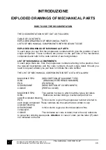
THE DOCUMENTATION IS SET OUT AS FOLLOWS:
TABLE OF CONTENTS
FUNCTIONAL DIAGRAM
DIAGRAM OF CONNECTIONS AND COMPONENTS
LIST AND POSITION OF CONNECTIONS AND COMPONENTS
FUNCTIONAL DIAGRAM
This diagram provides the co-ordinates of a component through letters along the
horizontal axis and numbers along the vertical axis and helps explaining its function
on the machine.
DIAGRAM OF CONNECTIONS AND COMPONENTS
This diagram provides references for connections and components of the pneumatic
equipment. The reference on the electrovalves indicates only the valve body while
the electromagnetic coils have the same denominations used in the electric
equipment.
LIST OF PNEUMATIC COMPONENTS
The list of components is set out as follows:
RIF. (REFERENCE) Components and connections are listed in this column in
alphanumerical order, while the pipes are listed according to their diameter.
PAG. (PAGE) In this column are given the pages where the component is used and
the page on which it is physically represented (in order to facilitate its finding and, if
necessary, its replacing).
DESCRIZIONE A short description of the component and of its function is given in
this column.
NUM. The amount of pieces of the components appears in this column.
TIPO The component type, or its features appear in this column, so that you will be
able to find the material by yourself.
FORNITORE The component’s supplier is indicated in this column.
NS. CODICE Our code or detail to be indicated in case of order of spare parts,
appears in this column. In case of order bring letter P where indicated.
MANUALE D’ISTRUZIONE PER L’USO E LA
MANUTENZIONE PULITRICE AUTOMATICA CM4S
52
File: 2240.doc - 03/11/03 14:27


