E)
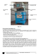
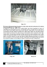
Motor and milling cutter pack holding group
(Dwg. A1.3)
It consists of a structure made of steel sheet details, assembled by means of intermittent weld,
aluminium plates and steel rods. A special electric motor with a long shaft has been fixed on this
structure, in order to permit to place up to 4 milling cutter packs. The milling cutter packs are
mounted directly on the motor shaft without any transmission. The motor shaft is supported at
the end to give a bigger rigidity and to eliminate the possible vibrations during the rotation and
processing phases. On the same structure has been mounted a safety guard for the milling
cutter packs made of electro-welded sheet, which can be opened in order to enable the
replacement of the milling cutter packs and that works also as exhaust hood for the chips
produced during processing.
F)
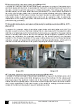
Group with locking device and upper cutting device for welding seal removal
(Dwg. A1.5) -
(Dwg. A1.6)
It consists of a structure made of aluminium sheet details with steel plates and rods. This
structure is used to carry out the frame locking, first at a low pressure for the operator’s safety
and then at a high pressure for the machining. It works also as a support for the upper cutting
device for welding seal removal and for the automatic profile recognition (optional). On this
structure are assembled: the pneumatic actuators for the vertical blocking, the pneumatic
actuator for the forward movement of the upper cutting device and, if the above mentioned
optional is present, all relevant limit switch sensors and linear potentiometers, which permit to
read the form and the dimensions of the profile composing the frame to be processed.
Dwg. A1.5 Dwg. A1.6
G)
Total safety guards for moving parts and working area
(Dwg. A1.1)
It consists of a structure made of steel sheet, assembled by means of intermittent weld, which
protects the working area and all other dangerous zones of the machine. On this safety guard
have been placed the electronic control unit of the machine as well as some control push
buttons and some signalling lamps. Limit switch controlled Inspection doors have been made to
carry out the replacement of the cutter’s packs, of the knifes for welding seal removal and to
accede to the internal components in case of maintenance works.
MANUALE D’ISTRUZIONE PER L’USO E LA
MANUTENZIONE PULITRICE AUTOMATICA CM4S
9
File: 2240.doc - 03/11/03 14:27


