Ignitor fitment
1. Set the adapter plate it into the distributor. Insert the provided hold down stud
through the plate and distributor housing.
2. Install the timing adjustment slide over the stud. Install the provided lock nut.
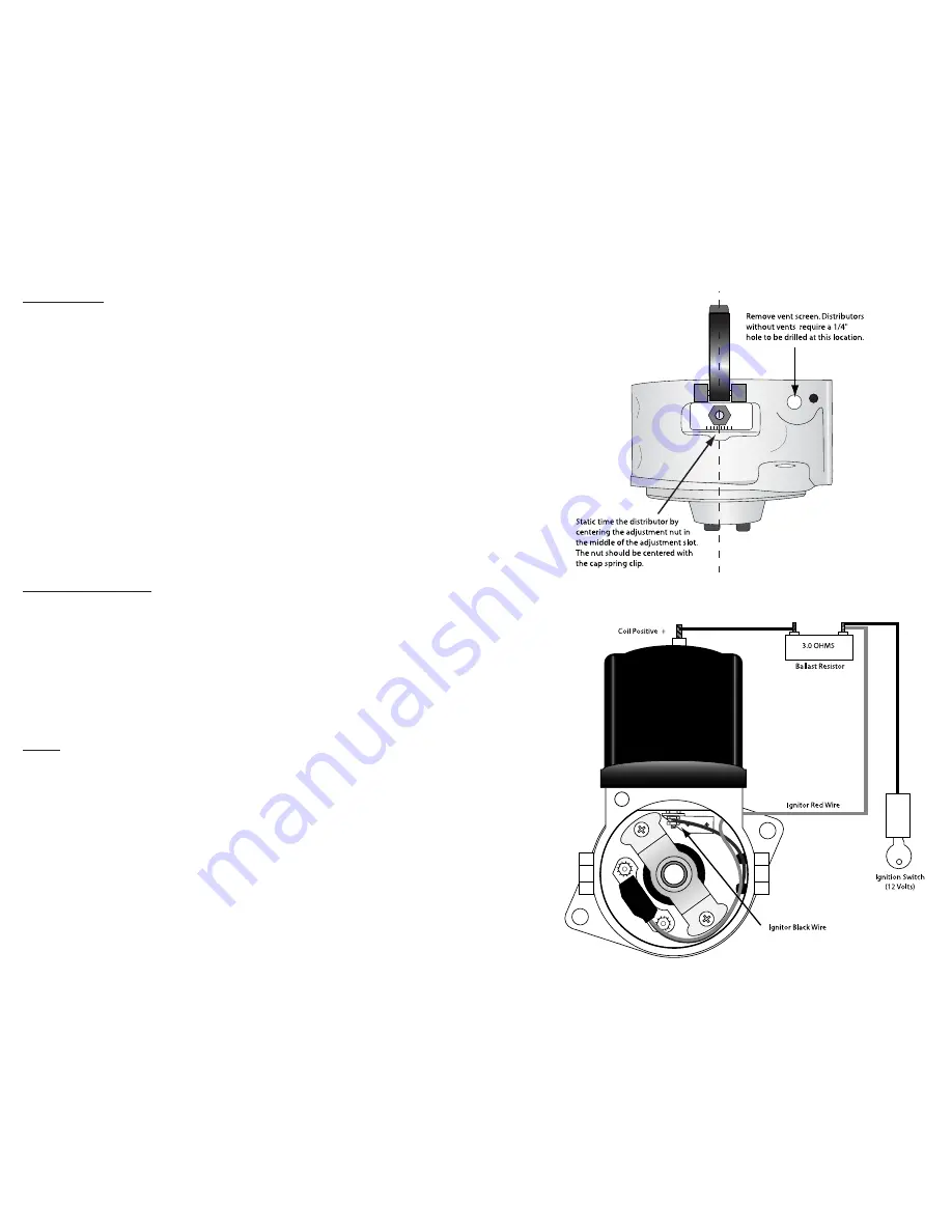
3. Static time the distributor by positioning the plate so that the slide is posi-
tioned in the middle of the adjustment slot. The adjustment nut should be
centered with the cap spring clip (See Illustration B). Tighten the nut once it
is aligned properly.
4. Install the plate retaining ring. The flat portion of the ring should be placed on
adjustment slot side of the distributor.
5. Install the ignitor module onto the mounting studs.
6. Tighten the module into place with the hardware provided.
7. Attach the black ignitor wire to the coil negative contact stud mounted on the
plate. Tighten the wire down with the provided nut. (See Illustration C)
8. Insert the red wire through the hole that was made in the distributor body.
9. Install the magnet sleeve onto the point cam.
10.Install the shim washer onto the distributor shaft.
11.Install the shaft support bracket. Spin the distributor shaft to align the bracket
and tighten in place with the 8-32 screws provided.
Distributor Installation
1. Install the rotor
2. Turn the rotor to the position that was noted prior to the removal of the dis-
tributor.
3. Place distributor into block and fasten in place with the original mounting
bolts. Note: Do not force the distributor into place. Check to make sure that
drive tang is properly aligned.
4. Install the distributor cap.
5. Install the coil and coil retaining bail.
6. Install the spark plug wires.
Wiring
Most stock and aftermarket coils are designed for six volt systems. These coils
have a primary resistance of approximately 0.6 ohms. and when used with the
Ignitor must be equipped with a ballast resistor. We recommend a resistor 2.4
ohms or greater to prevent ignition failure. Coils having a 3.0 ohm primary
resistance can be used without an external resistor.
1. Install the ballast resistor.
2. Attach the ignition switch wire and the Ignitor red wire to one side of the
resistor. (See Illustration C)
3. Using 18 gauge wire or larger, connect the opposite side of the resistor to
the coil positive terminal.
Illustration C
Illustration B


