8
Switch wiring scheme
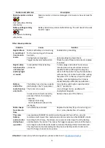
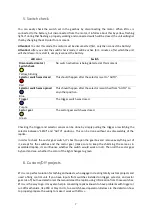
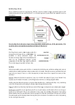
ETU++ socket has 4 pins for 4 signal wires. Of those, 3 are for selector, trigger, and sector gear cut-off
(information about cycle end) and the 4
th
is a common ground, to which all the switches must be
connected.
Do not allow the motor wires to get into (uninsulated) contact with any of the signal wires. This
would result in an immediate and permanent failure of the device!
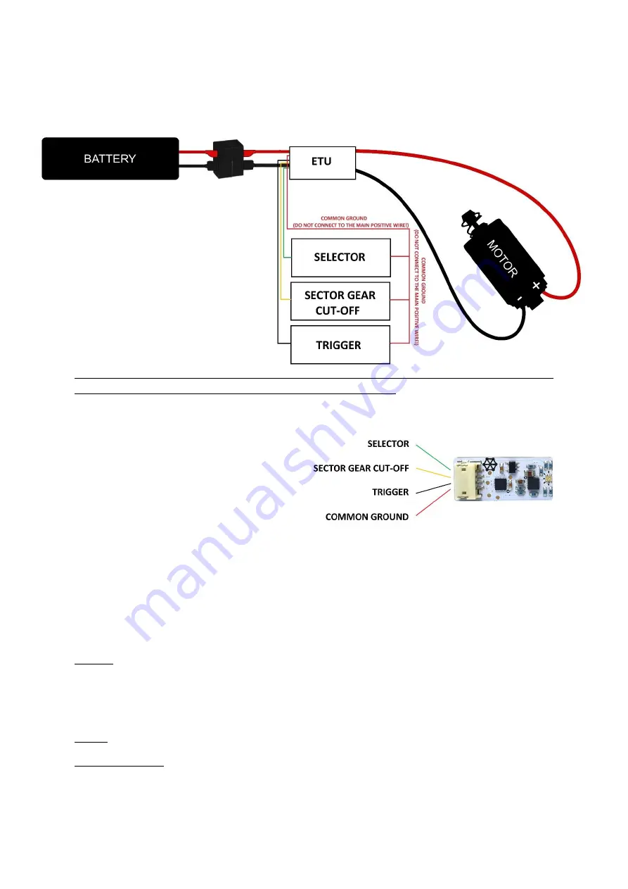
Plug
The Plug that is used in G&G replicas with ETU
and works with Perun ETU++ is
JST ZHR-4
. It is
available in many electronic shops. We
recommend using plugs with pre-installed wires
that can be lengthened, because correct
preparation of the bare plug might be difficult.
The correct plug wiring order is shown here.
Switches
Almost any switch can be used, as ETU++ is resistant to contact bounce, while low voltage and current
used to detect switching allows using a wide variety of models. Therefore, use any switches that will
best suit your project. Here is a short description, of what does ETU++ expect from each of the
switches:
Selector
: When the switch is closed, ETU++ sees it as “AUTO” and when it’s open, it sees “SEMI”
. This
is pretty much irrelevant however, as the firing modes in ETU++ are freely programmable.
Please note that the safe mode can only be achieved either by a mechanical safety, or by sacrificing
one of the firing modes and making it safe by programming electronic safety.
Trigger: Switch should be closed by the movement of the trigger and opened upon releasing the trigger.
Sector gear cut-off: Once per gearbox cycle ETU++ should receive an information from a sector gear
switch, or cut-off switch. This can be achieved in many ways, but probably the easiest is by reading
either directly from the cut-off knob of the sector gear or from the cut-off lever. The amount of time
the sector gear switch is being pressed during the cycle is irrelevant, the electronic unit is only looking
for the closing of the switch.


