V
IDBLOX
3G-SL
AND
3G-NE
RX
M
ODULE
Publication 81-9059-0667-0, Rev. C
March 2011
Proprietary Information of PESA
3-6
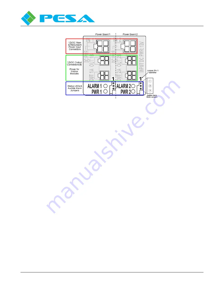
Figure 3-5 Power Distribution Module
3.6
P
OWER
D
ISTRIBUTION
/F
AN
M
ODULE
R
EDUNDANT
P
OWER
,
A
LARMS AND
LED
S
As shown by Figure 3-5, there are two power input connectors – one for connection to the main external
power supply, and the second for connection to a second external power “brick” for automatic power
redundancy. One external power supply connected to either of the power input connectors can supply
power for up to four Vidblox modules. While some load sharing may occur when a redundant power
supply is used, the second supply, if connected, serves as a self-switching back-up power supply in the
event the main supply should ever fail.
The power distribution module contains two circuit boards each with one input power connector, two
output power connectors, status monitor LEDs and audible alarm mode select pins. In Figure 3-5, these
are identified as Power Board 1 and Power Board 2. Even though the input power connector, status
LEDs and alarm jumpers are specific to board 1 or 2, all four output connectors are always powered and
monitored for loss of output.
There are two status LEDs on each board identified as Alarm and Power (PWR). When power from an
external supply is attached to either of the input connectors the green PWR LED associated with the
board lights as an indication that power is present. The ALARM LED is red and when lit indicates one
of two possible error conditions is occurring with the distribution module:
•
There is a failure with one or both of the cooling fans
•
There is a failure of at least one of the power output connections
Summary of Contents for VIDBLOX 3G-NE RX
Page 57: ......


