14
VB 230/400-25
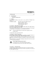
12.3 Parameter settings
Sequence of commissioning:
1. Disconnect the plant from the supply mains.
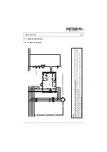
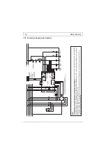
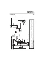
2. Connect the current measuring instrument between the braking device, terminal „2T1“, and
the motor terminal „U“.
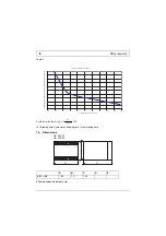
3. Turn the potentiometer "I" to a position in the first third of the adjustment range (factory
setting) (please see chapter 7 on page 8).
4. Switch on the plant.
5. Initiate braking by switching the motor contactor ON and OFF.
Note:
The adjustment of the braking current requires a moving-iron instrument.
Clamp-on probes or digital multimeters may only be used if they can
measure the true r.m.s..
Adjusting the braking current
The braking current is to be adjusted to a value as small as possible, in order to avoid
unnecessary heating of the power semiconductors and the motor. This is especially important in
the case of frequent operation. We recommend to limit the maximum braking current to 2.5 times
the rated motor current.
The requested braking torque is to be adjusted with the potentiometer "I". It is important that the
braking current does not exceed the rated device current which is indicated on the nameplate of
the device.
A braking current higher than the rated device current causes a flashing „ready“-LED. In this
case, the potentiometer „I“ has to be turned back to a position where the flashing goes over into a
steady light.
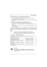
The braking current can be measured with a clamp-on ammeter (True RMS) or a corresponding
moving iron amperemeter at the output terminal "4T2" of the braking device.
Attention:
When the „ready“-LED is flashing, the current flowing in the device is approx.
1.3 times as high as the rated device current. Operating the device with the
LED flashing and utilizing the permissible braking frequency will cause that
the braking device is overloaded and consequently destroyed.
Adjusting the braking time
An adjustment is not necessary, since 1.5s after the motor has come to a standstill the braking
current will be automatically switched off.
If during the maximum braking time (15s in the case of standard devices) no standstill is detected,
the braking current will be switched off after this time. This case will be indicated by an opening of
the potential-free contact (X7, X8).
Note!
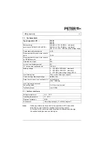
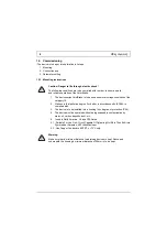
All data sheets and commissioning instructions are available on our
homepage at
www.peter-electronic.com
.


