20
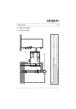
VB 230/400-25
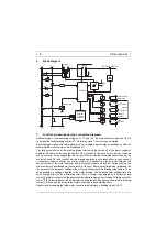
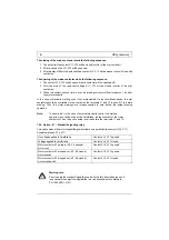
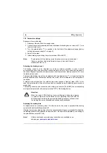
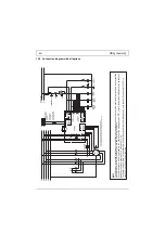
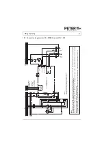
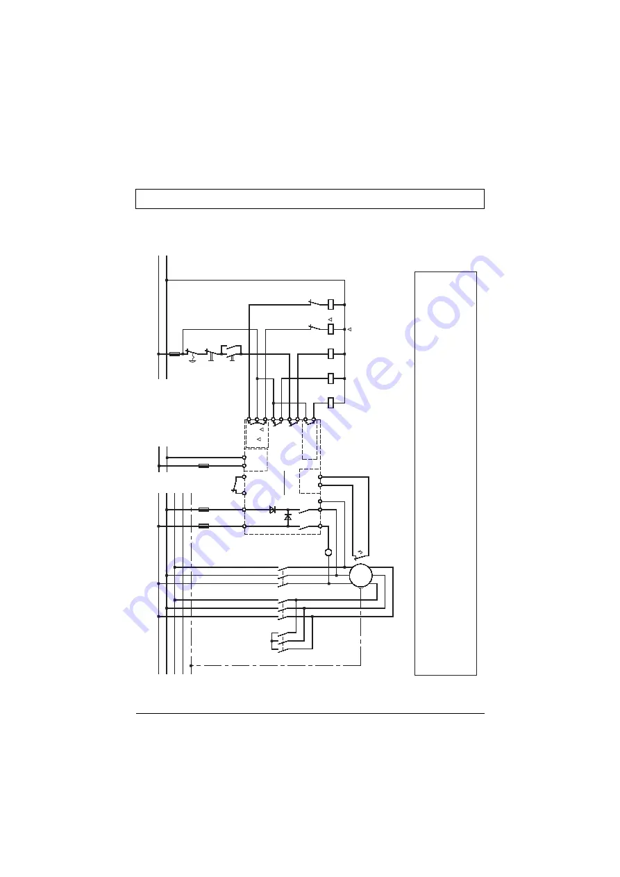
15.2 Connection diagram with all options
Op
tio
n
Mo
to
r
te
m
per
at
ur
e
X1
4
X1
5
X6
X5
X8
X7
X1
3
X1
2
X1
1
Fa
ul
t
si
gn
al
ling
re
la
y
In
te
rloc
ki
ng
co
nt
ac
t
Op
tio
n
Y
EM
ER
G
EN
C
Y
O
FF
OF
F
ON
K1
D1
K1
K2
K3
K3
K2
Y
Fa
ul
t
si
gn
al
lin
g
re
la
y
Mo
to
r
co
nt
ac
to
r
Y
C
ont
ac
to
r
C
ont
ac
to
r
X3
X4
St
ar
t
1L1
3L2
2T
1
4T2
6T3
Ve
rs
iB
ra
ke
L1.
1
N.
1
C
on
tro
l v
olt
ag
e
L1
L2
L3
N
PE
K3
K2
K1
U1
V1
W
1
V2
U2
W2
M 3
~
K1
D2
X1
6
X1
7
Y
Op
tio
n
St
ands
til
l
si
gn
al
ling
re
la
y
St
an
ds
till
si
gn
al
lin
g
re
la
y
A
M
ov
ing-
iro
n
in
st
ru
m
en
t
X1
X2
AC
AC
Op
tio
n
w
ide
v
ol
ta
ge
ra
nge
R
eq
ui
red
in
th
e
cas
e
of th
e
w
id
e v
ol
ta
ge
ra
nge
opt
io
n
Th
e
co
rre
ct
ter
m
ina
l-p
has
e
m
us
t b
e
en
su
re
d
be
tw
een
th
e
br
ak
in
g
dev
ic
e
inpu
t (
L1,
L
2)
ans
the
b
ra
ki
ng
d
ev
ic
e
ou
tp
ut
(T
1,
T2
).
Th
e
he
igh
t o
f t
he
co
nt
ro
l vo
lta
ge
is
o
n
th
e
na
m
ep
la
te
an
d
on
the
te
rm
in
al
s.
The limit values for emitted according to the applicable device standards do not rule out the possibility that receivers and su
sceptible
electronic devices within a radius af 10m are subjected to interference. If such interference, which is definitely to the operation af the braking devices "VB", occurs, the emitted interference can be
reduced
taking appropriate measures. Such measures are, e.g.: To connect reactors (3mH) or a suitable mains filter in series before the braking device, or to connect X-capacitors (0,15
μ
F) in
parallel to the supply voltage terminals.
EMC

