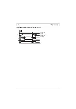
VB 230/400-25
13
12.2 Connection
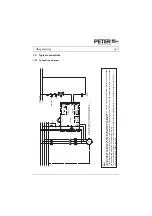
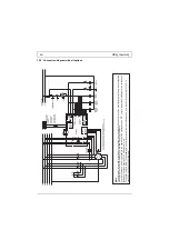
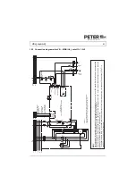
The braking device is to be installed according to the attached connection diagram. For other
connections please consult Peter electronic GmbH & Co. KG.
Note:
Further connection proposals for special circuit arrangements are available
via our homepage at
www.peter-electronic.com
.
Note:
Prior to putting the motor brake into operation, the wiring has to be checked.
To ensure a reliable function it is necessary to comply with the interlocking conditions:
1. To initiate braking, a potential-free normally closed contact of the main contactor is
necessary, i.e., when the motor contactor is dropped out, the terminals X3, X4 (start) of the
braking device are connected.
2. The interlocking contact of the braking device (terminals X5, X6 (lock)) has to be looped
into the control circuit of the motor contactor, so that the motor contactor
cannot
pull in
during braking.


