VB 230/400-25
15
13. Dimensioning rules
13.1 Dimensioning of braking contactors
The braking contactor is switched on or off via a control contact of the braking device (no-load
switching).
When selecting the braking contactor, it must be ensured that the contacts are able to carry the
maximally occuring braking current (nominal/rated device current). Therefore, the value „conven-
tional thermal current“ (I
th
) is decisive when selecting the braking contactor.
If this value is not indicated, the rated operational current for AC1-operation may be used instead.
Tip:
By connecting contacts in parallel it is often possible to use a lower-priced
contactor of a smaller design.
13.2 Dimensioning of pre-fuses
Basically, two types of fuse protection are available for the user:
1. Fusing according to allocation type „1“, DIN EN 60947-4-2.
After a short circuit, the braking device is allowed to be inoperative.
2. Fusing according to allocation type „2“, DIN EN 60947-4-2.
After a short circuit, the braking device must be suitable for further use. However, there is
the danger that the contacts of the braking relay (braking contactor) weld. Therefore, if
possible, these contacts are to be checked prior to reconnecting the device to the supply. If
this check cannot be carried out by the user, the device has to be returned to the producer
in order to have it checked.
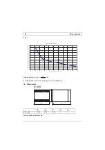
The following dimensioning information refers to the below operating conditions:
•
Use of standard asynchronous motors
•
Braking time not exceeding 20s, for braking devices up to 36A.
•
Braking time not exceeding 40s, for braking devices from 40A up.
•
Braking current not exceeding 2.5x I
NOM
of the motor.
•
Cyclic duration factor (c.d.f.) not exceeding the value indicated in the data sheet.

