VB 230/400-25
19
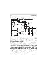
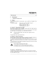
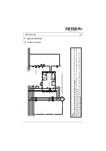
15. Typical connections
15.1 Connection diagram
Op
tion
M
oto
r
temp
erature
X14
X15
X6
X5
X8
X7
X1
3
X1
2
X1
1
Fau
lt
signalling relay
Interlock
in
g
contact
Op
tion
Y
EMERGENCY
OFF
OFF
ON
K1
K1
M
oto
r
contactor
X3
X4
St
ar
t
1L
1
3L
2
2T
1
4T2
6T3
Ve
rsiBra
ke
L1
.1
N.1
Control voltage
L1
L2
L3
N
PE
K1
M 3
~
K1
F4
F1
F2
F3
X17
X16
Option St
an
ds
til
l
signalling relay
Y
The correct te
rmi
nal-phase conn
ec
tio
ns must b
e ensured betwee
n
the braking de
vice input (L1, L2) a
nd
the b
raking device o
utput
(T1,
T2).
VB 230
- .
..
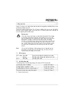
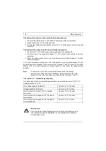
The limit values for emitted according to the applicable device standards do not rule out the possibility that receivers and su
sceptible
electronic devices within a radius af 10m are subjected to interference. If such interference, which is definitely to the operation af the braking devices "VB", occurs, the emitted interference can be
reduced
taking appropriate measures. Such measures are, e.g.: To connect reactors (3mH) or a suitable mains filter in series before the braking device, or to connect X-capacitors (0,15
μ
F) in
parallel to the supply voltage terminals.
EMC

