VB 230/400-25
21
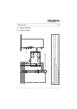
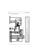
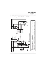
15.3 Connection diagramm for VB...-25DB (UL), cut off 1L1, 3L2
EMERGENCY OFF
OFF
ON
K1
K1
K2
K3
K3
K2
Y
Motor
cont
acto
r
Y
contac
tor
contac
tor
L1.1
N.1
Control
voltage
L1
L2
L3
N
PE
K3
K2
K1
U1
V1
W1
V2
U2
W2
M 3
~
X6
X5
X8
X7
X13
X12
X1
1
Fault signal
ling
Interl
oc
king
Opti
on
Y
X3
X4
St
art
1L1
3L2
2T1
4T2
6T
3
VB ...-25
D
B (UL)
In
this circuit option "S"
is not
avail
able.
Y
X17
X16
K1
X1
X2
Opti
on
Wide-voltage
ran
ge
F1
F2
F5
K4
F3
Attention: The correct terminal-phase connecti
ons must be ensu
red between the
braking device input (L1,L2) an
the braking device output (U,V)
K4
AC
AC
Required i
n the case
of the w
ide voltage
range option
The height of the control
voltage
is on the nameplate and on
the terminal
s.
cut of
f
cut off
The limit values for emitted according to the applicable device standards do not rule out the possibility that receivers and su
sceptible
electronic devices within a radius af 10m are subjected to interference. If such interference, which is definitely to the operation af the braking devices "VB", occurs, the emitted interference can be
reduced
taking appropriate measures. Such measures are, e.g.: To connect reactors (3mH) or a suitable mains filter in series before the braking device, or to connect X-capacitors (0,15
μ
F) in
parallel to the supply voltage terminals.
EMC

