background image


APPROVED LUBRICANTS 

Supplier 


U.K. Winter & Summer 

Up to 30°C (86°F)  


Tropical  

Above 30°C (86°F)  


Shell Oil Co. Ltd. 


Rotella SX 10W 
Rotella TX 10W 
Rotella TX 10W/30 
X-100 10W 
Talona Oil 10W 


Rotella SX 20 20W 
Rotella TX 20 20W 
Rotella SX 20W/40 
Rotella TX 20W/40 
Super Oil 
Tractor Oil Universal 


Mobil Oil Co. Ltd. 


Delvac Special 10W/30 
Delvac 1210 


Delvac Special 10W/30 
Mobiliand Universal 
Mobiloil 20W 30 
Delvac 1220 

Mobilgard 212 


B.P. Companies Ltd 


Vanellus 10W 
Super Visco-Static 10W/40 


Vanellus 20W 
Vanellus 20W 30 
Super Visco-Static 20W/50 
Energol 1C M20W 
Tractor Oil Universal 20W/30 

Castrol Ltd. 


Deusol CRI 10 
Deusol CRB 10 
Deusol CRB 10W/30 
Castrol CRI 10 
Castrol CRB 10 
Agricastrol Multi-Use 10W/30 


Deusol CRI 20 
Deusol CRB 20 
Deusol CRB 10W/30 
Oeusol CRM 
Castrol CRB 20 
Castrol 210 MX 
Agricastrol Multi-Use 20W/30 


Esso Petroleum Co 
Ltd. 


EssolubeHD 10W 
Essolube HDX 10W 
Essolube 0.3 HP 10W 
Essolube D-3 10W 
Essolube HDX 10W/30 
Motor Oil 10W 


Essolube HO 20W 
Essolube HDX 20W 
Essolube D-3 HP 10W 
Essolube D-3 10W 
Essolube HDX 10W/30 
Motor Oil 20W 


Caltex (UK) Ltd. 


Supreme Five Star 10W/30 
Custom Five Star 10W/30 
Five Star 10W 
RPM Delo200 10W/30 
RPM Delo 200 10W 
RPM Delo 100 10W 


Supreme Five Star 10W/30 
Custom Five Star 10W/30 
Five Star 20/20W 
RPM Delo200 10W/30 
RPM Delo 200 20/20W 
RPM Delo 100 20/20W 


Chevron International 
Oil Co Ltd. 

Delo Special 10W 
Delo200 10W 

Delo Special 20/20W 
Delo 200 20/20W 

Texaco Ltd. 


Ursa Extra Duty 10W 
Ursa Extra Duty 10W/30 
Havoline 10W 
Havoline 10W/40 


Ursa Extra Duty 20W 
Ursa Extra Duly 10W/30 
Havoline 20/20W 
Havoline 10W/40 


Gulf Oil (G.B.) Ltd 


Gulflube XHD 10W 
Gulflube XHD 10W/30 
Multi-G 10W/30 


Gulflube XHD 20/20W 
Gulflube XHD 10W/30 
Mulli-G 10W/30 
Superfleet 20W/30 


Summary of Contents for AB1W

Page 1: ...P OF THE GRIP AND NOT ROUND IT KEEP THE HANDLE AND SHAFT CLEAN AND LUBRICATED TO ENSURE EASY WITHDRAWAL OF HANDLE DO N0T REMOVE GTUARDS KEEP CLEAR OF HOT MOVING OR ELECTRICAL PARTS IF THE ENGINE IS INSTALLED IN AN ENCLOSED SPACE VENT THE EXHAUST FUMES TO ATMOSFHERE WHEN TESTING FUEL INJECTORS DO NOT DIRECT THE SPRAY AT ANY EXPOSED PART OF THE BODY IT CAN PENETRATE THE SKIN Publication No 355791 PE...

Page 2: ...sel Engines TYPES AB1W and AC1W 3773 This book will help the user to get the best results from the engine No engine wilt run without care but it wilt give good service if given the attention described in this book ...

Page 3: ... When purchasing parts or giving instructions for repairs customers should in their own interest always specify Genuine Petter Parts Parts that have not been supplied by the Petter organisation cannot be relied upon for correct material dimensions or finish Fetters cannot therefore be responsible for any damage arising from the use of such parts and the guarantee will be invalidated In your own in...

Page 4: ...rom sump and refill with clean oil c Check fuel filter d Check all nuts bolts etc for tightness Requests for parts and service should be directed to Overseas The appointed Petter agent or dealer in the territory United Kingdom Petters Ltd Service Division Phone Hamble 2061 Hamble Telex 47626 Southampton Telegrams S03 5NJ Petter Hamble Telex or Service Depots at Petters Ltd Service Depot Broomhill ...

Page 5: ...C 2701 to 3300 rev min 29 bef ore TDC 3301 to 3600 rev min 34 bef ore TDC Variable speed 29 before TDC Inlet valve opens 13 before TDC Inlet valve closes 38 after BDC Exhaust valve opens 38 before BDC Exhaust valve closes 13 after TDC Reduction gear ratio 6 1 Fuel tank capacity engine mounted 9 pints 5 13 litres Oil capacity 31 4 pints 1 9 litres Lubricating oil See approved list Fuel A high grade...

Page 6: ...to 3300 rev min 32 be fore TOC 3301 to 3600 rev min 33 be fore TDC Variable speed 28 before TDC Inlet valve opens 13 before TDC Inlet valve closes 38 after BDC Exhaust valve opens 38 before BDC Exhaust valve closes 13 after TDC Reduction gear ratio 6 1 Fuel tank capacity engine mounted 9 pints 5 13 litres Oil capacity 43 4 pints 2 7 litres Lubricating oil See approved list Fuel A high grade light ...

Page 7: ...h diameter fitted 0 8753 0 8757m 22 233 22 243mm Reduction gear power take off shaft end float 0 002 0 005in 005 0 13mm Cylinder rebormg diameters Standard 3 000 3 001 m 76 20 76 23mm Oversize 0 020in 3 020 3 021 m 76 71 76 73mm 0 030in 3 030 3 031 in 76 96 76 99mm 0 040m 3 040 3 041 m 77 22 77 24mm Crankshaft regnnding diameters Main journal and crankpin Standard 1 6250 16245m 41 275 41 262mm Und...

Page 8: ...ion body 152 07 Crankshaft and camshaft extension shaft screw 141 94 Crankshaft gearwheel retaining screw 273 73 Camshaft gearwheel retaining screw 273 73 Starting handle shaft retaining screw Raised Hand Starting 273 73 Mounting plate screw 4 1 Hand Starling 182 49 Sliding plate locating screw 41 Hand Starting 182 49 Sliding plate stop screw 4 1 Hand Starting Flywheel end 81 10 Gearwheel retainin...

Page 9: ...l CRM Castrol CRB 20 Castrol 210 MX Agricastrol Multi Use 20W 30 Esso Petroleum Co Ltd EssolubeHD 10W Essolube HDX 10W Essolube 0 3 HP 10W Essolube D 3 10W Essolube HDX 10W 30 Motor Oil 10W Essolube HO 20W Essolube HDX 20W Essolube D 3 HP 10W Essolube D 3 10W Essolube HDX 10W 30 Motor Oil 20W Caltex UK Ltd Supreme Five Star 10W 30 Custom Five Star 10W 30 Five Star 10W RPM Delo200 10W 30 RPM Delo 2...

Page 10: ... fuel system if applicable Repair or renew the pipe or tighten the connection Fit new fuel filter element Fit new nozzle Fit new pump Free and clean tappet Engine will not start Poor compression Valves sticking Cylinder head loose Cylinder head gasket blown Piston rings stuck in groove Worn cylinder and piston Valves not sealing properly Free the valves Tighten all nuts Fit new gasket Check rings ...

Page 11: ...e starts but fires intermittently or soon stops Dirty exhaust Blocked exhaust pipe or similar Clean out Faulty fuel supply Faulty fuel pump Faulty injector nozzle Unsuitable fuel Fit new pump Fit new nozzle Drain the fuel system and fill with correct fuel Out of adjustment Valve clearances incorrect Fuel timing incorrect Adjust Adjust Engine lacks power and or shows dirty exhaust Dirty engine Bloc...

Page 12: ...ve valve clearance Lubricating oil failure Check for leaks or blockages Remove and clean Check and tighten fittings Replace rotor and check pump Replace seal and check pump Reduce the load Adjust Check the engine and lubricating oil system for damage If in order top up sump and check running Speed swrg Overheating Air in fuel pipes Governor slicking See above Bleed the system if applicable Check t...

Page 13: ...and a flexible coupling fitted 3 Exhaust a An exhaust manifold flange is available from Petters Ltd or their agents and is tapped to enable a threaded exhaust pipe to be fitted b Exhaust pipe sizes are as follows i AB1W This flange is tapped 1in BSP and is suitable for exhaust pipe lengths up to 18in 457mm For lengths from 18in 457mm to 10ft 3m and from 10ft 3m to 20ft 6m the manifold must be adap...

Page 14: ...ater flow is interrupted iv IT IS IMPORTANT that the vertical distance between the water pump if fitted and water supply is no more than 2ft 61 0 mm By fitting a small reservoir to the suction side of the pump and supplying water through a hose of no more than 3 8 in 9 5mm bore the distance may be increased to 10ft 3m A suitable reservoir and hose is available from Petters Ltd or their agents v To...

Page 15: ... remain in the cooling system for more than six months or the corrosion inhibitor may deteriorate When necessary drain the cooling system and refill with a new antifreeze mixture fig 1 viii Do not mix different grades of anti freeze and always top up with a mixture of the same strength Make sure that the mixture is suitable for the coldest conditions likely to be encountered 6 Lubrication a The en...

Page 16: ...rs etc have effective sealings c Tank cocks for withdrawing fuel should be fitted a short distance above the base enabling clean fuel to be withdrawn without disturbing water or sediment d To ensure proper working of the fuel system the fuel must always be CLEAN e Fuel should be allowed to settle before use Sludge or water at the bottom of the container must not be used Due to increased engine rep...

Page 17: ...e engine at a constant speed irrespective of load variations and will be either a fixed speed type governing the engine at its rated speed only or a variable speed type allowing the governed speed to be varied between idling and full rated speed The centrifugal forces on the governor balls are transmitted to the fuel pump rack These forces which vary with the speed of the engine are balanced by an...

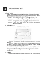
Page 18: ...el end Rope starting at end remote from flywheel 10 Pulley drive Fig 2 Allow for 21 2 increase between centres When belt drives are used the belts should be as close to the engine as possible To prevent damage to new vee belts when fitting the distance between the centre of the engine pulley A and the driven pulley B must be capable of a reduction from the designed running position Provision must ...

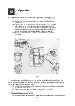
Page 19: ...the level always falls slightly after initial circulation c A81W Unscrew the nut on the air cleaner cover remove the cover Fig 3 and element and dip the cover In a bath of clean lubricating oil Allow the cover to drain Replace the element and cover making sure that the element is correctly seated on the sealing rings d Lift the decompressor lever A and turn the engine fifteen revolutions to help c...

Page 20: ...esistance until the injector has squeaked ten times This is unnecessary with a warm engine ii Wind the rope round the starting pulley in the direction of rotation The end of the rope should be in the pulley from two to two and a half turns WARNING THE ROPE SHOULD NOT BEWOUND ROUND THE OPERATOR S WRIST iii Make sure that the decompressor lever is disengaged and then pull the rope smartly until it u...

Page 21: ...tery power is low when electric starting Proceed as follows i Remove the priming plunger P ii Fill the priming chamber with engine oil NOT fuel iii Replace the priming plunger and press down iv It is advisable to keep a quantity of lubricating oil in a suitable container for this purpose v Start in the normal manner b Should the engine fire and then stop prime again and release the overload stop l...

Page 22: ... stop the engine by allowing the fuel tank to run dry c DON T remove or alter the setting of the overload stop or operate the overload stop lever when the engine is running This will cause overheating excessive wear and possibly piston seizure d DON T forget to grease the starting handle shaft Make sure the starling handle can be freely withdrawn e DON T forget to drain the cooling system before l...

Page 23: ...nuts must NOT be tightened when the engine is hot b Make sure the fuel tank filler cap vent hole is clear c Clean the air cleaner paper element type d Clean out deposit from exhaust system e Drain the sump flush out with flushing oil and refill with new oil Paraffin may be used if flushing oil is unobtainable but the engine must not be run with paraffin in the sump f Check the fuel system for leak...

Page 24: ...ter and fit new corrosion inhibitor union d Fit new cylinder head gasket 24 Every 2000 hours a Decarbonise b Clean out piston oil return holes Check cylinder bore wear c Examine the crankshaft bearings and renew if clearance is excessive d Clean the oil pump strainer e Remove the fuel injector and test spray If in order replace without further interference ...

Page 25: ... Disconnect the cooling water outlet hose and remove the plug and pipe fittings from the cylinder head e By inserting a piece of wire through the various orifices in the cylinder and cylinder head rake out any silt that has collected in the cooling system This should be carried out while flushing with clean fresh water preferably under pressure f The use of a descaling agent wilt be of assistance ...

Page 26: ...nsure that the pump shaft does not touch the pump cover when the water pump is replaced If it does extra shims must be added between the adaptor plate and the pump body d Replace the impeller on the shaft and refit joint and cover plate The joint must be positioned so that the camplate is covered e Replace the inlet and outlet pipes 29 Decarbonising A carbon deposit forms on piston and cylinder he...

Page 27: ... at the end of the valve guide bores are free from carbon e Thoroughly clean the valves and examine the valve seats If these show signs of pitting they should be ground in f Make sure the valves are seating properly Leaking valves cause loss of compression and difficult starting g DO NOT remove the air cell from the cylinder head If a carbon deposit has formed in the air cell nozzle it may be clea...

Page 28: ...e valve backwards and forwards on its seating exerting a gentle but firm pressure c Periodically lift the valve from its seating and give it half a turn Thus ensuring that the grinding paste is evenly spread d It is unnecessary to continue grinding once the faces of the valve and its seating have a clean even matt surfaced appearance A polished surface must not be expected and is unnecessary e Was...

Page 29: ...ad nuts using a torque spanner set to the figure shown under Technical Data Proceed as follows i Screw down each cylinder head nut until finger tight ii Tighten each nut a quarter of a turn at a time working diagonally across the cylinder head until all the nuts are tight h Adjust the valve rocker clearances see Technical Data i Tighten the injector stud nuts using a torque spanner set to the figu...

Page 30: ...e see Technical Data the rings should be renewed To measure the gaps remove the rings from the piston noting the order of assembly and which ring face is uppermost b Remove all the carbon deposit from the rings and ring grooves The small holes A in the scraper ring grooves should receive attention as their purpose is to return excess oil to the sump c Insert the piston into the cylinder bore with ...

Page 31: ...o remove all traces of carborundum f To allow the piston rings to bed in satisfactorily it is recommended that the engine be run on half load whenever possible after overhaul 41 To replace cylinder and piston a Generally reverse the instructions for removal and dismantling b Take care that the piston ring gaps are not in line but well distributed around the piston circumference c Replace the shims...

Page 32: ... in position and should not be scraped or bedded in neither should shims of any description be fitted If the faces of the connecting rod or its cap are filed the rod becomes useless regarding replacement bearing shells When fitting make sure that the connecting rod bore the outside of the shells and their split faces are clear e Connecting rods and caps are stamped with an assembly serial number a...

Page 33: ...rd 47 4 1 hand starting gear end a To remove i Remove the starting gear guard ii The gearwheels can now be greased using a high melting point grease The sliding plate assembly locating screws and starting handle shaft recess can be lightly oiled without further dismantling iii Remove the starting gearwheel retaining clip and circlip And remove the gearwheel iv Remove the crankshaft extension shaft...

Page 34: ...berally oil the chain wheels with Shell Ensis 20 oil or equivalent and pack the clutch with water resistant grease c To replace i Generally reverse the instructions for removal ii IT IS IMPORTANT that the chainwheel and clutch assembly is fitted the correct way round When fitting this unit ensure that when turned clockwise the clutch binds and when turned anti clockwise the clutch is free iii Tigh...

Page 35: ...ankshaft maintenance a Carefully examine the bearing journals and crankpin They should be free from score marks and ovality should not exceed the maximum see Technical Data b If these defects are present the crankshaft should be reground to the diameter shown under Technical Data and undersize bearings fitted c Carefully clean out the oil holes and make sure they have radiused edges 53 Main bearin...

Page 36: ... gearwheels make sure that the teeth marked with dots are in their relative positions g Tighten the crankshaft gearwheel retaining screw and extension shaft screws if fitted using a torque spanner set to the figure shown under Technical Data h AC1W Proceed as follows i Loosely fit the crankcase to rocker box oil pipe at the crankcase end Feed the crankcase to main bearing housing oil pipe through ...

Page 37: ...ine onto its side to prevent the tappets from falling into the sump g Remove the extension shaft from the camshaft gearwheel if fitted h Remove the screws A retaining the camshaft thrust plate These are accessible through holes in the gearwheel Withdraw the camshaft and gearwheel assembly from the gear end of the engine i The gearwheel is a tight fit on the camshaft To fit a new thrust plate remov...

Page 38: ...nor assembly to the crankcase and withdraw it 59 Crankcase breather maintenance Under normal circumstances the breather assembly will not require maintenance However if removal is necessary proceed as follows a Drain and remove the fuel tank b Remove the breather pipe cover and valve c Remove the breather housing and seal from the crankcase A special tool for this purpose is available from Petters...

Page 39: ...remove the lever The spindle and return spring P can now be withdrawn from the inside of the crankcase DO NOT loosen the screw M clamping the overload stop N to the spindle on AB1W engines 61 Governor and linkage maintenance Fig 12 a Thoroughly clean all parts in paraffin or clean fuel paying particular attention to all bearings and governor balls b Examine the faces of the governor sliding and ro...

Page 40: ...ew fuel injection pump e If the speeder spring adjuster on variable speed engines has been disturbed check the distance from the crankcase boss to the end of the adjuster this should be 5 8in 16mm 63 Lubricating oil system Fig 13 a The lubricating oil system is as follows i A rotary oil pump A is mounted in the crankcase at the gear end The pump is driven by a gear from the camshaft ii Oil is draw...

Page 41: ...lement tighten the centre bolt using a torque spanner set to the figure shown under Technical Data 65 Oil pump strainer a To remove i Drain oil from the sump ii Remove sump iii Remove the centre bolt and spring plate and remove the strainer b To clean wash the strainer in clean paraffin or fuel c To replace generally reverse the instructions for removal making sure that the strainer is correctly s...

Page 42: ... is manufactured to very fine limits IT REQUIRES EXTREME CARE AND ABSOLUTE CLEANLINESS IN HANDLING d Should any part of the fuel system including pipes be removed from the engine it should be placed n a clean container which is filled with clean fuel NO FILING GRINDING SCRAPING OR SAWING SHOULD BE CARRIED OUT WITHIN A PEW YARDS OF DISMANTLED FUEL INJECTION EQUIPMENT e Replace the equipment wet No ...

Page 43: ...ibration by the manufacturers and only the delivery side may be dismantled The pump control side must NOT be dismantled and should be returned to the manufacturers or to Petters Ltd or their agents for servicing a Delivery side i Thoroughly clean the exterior of the pump ii Unscrew the delivery union body A lift out the delivery valve spring B and the delivery valve C iii Withdraw the delivery val...

Page 44: ...valves cause loss of fuel injection pressure and difficult starting c Make sure the rack is free throughout its travel 75 To replace fuel injection pump Fig 14 a Generally reverse the instructions for removal and dismantling b Thoroughly clean all parts in clean fuel and assemble wet c The sealing ring F should be fitted over the lower shoulder of the union body A before the union body is screwed ...

Page 45: ...am is away from the fuel pump housing and turn the engine until the exhaust or inlet valve is open k Make sure that the fuel pump rack ball engages with the fuel pump operating lever fork and that the correct number and thickness of shims is fitted between the pump and the crankcase l IMPORTANT New fuel injection pumps require special fitting instructions and these are given in the following parag...

Page 46: ...670m 170mm from the gear cover locating face A special tool for adjusting the cam is obtainable from Petters Ltd or their agents fig 15 The overload stop lever must be held against its stop during any adjustment to the cam v With the stop run lever in the stop position i e vertical move the fuel pump operating lever fully out by pulling the spring until the fuel pump has reached its stop position ...

Page 47: ...the engine from idling to full speed as quickly as possible without load and watching for exhaust smoke If smoke occurs move the overload stop cam in a CLOCKWISE direction by a small amount and repeat the acceleration test Repeat the procedure until no smoke occurs NOTE Variable speed engines and some fixed speed engines are fitted with special fuel injection pumps Quote the type required when ord...

Page 48: ...nk and bleed the fuel filter if fitted A small stream of fuel should now flow from the pump to injector pipe h Engage the decompressor lever and turn the flywheel slowly by hand in a clockwise direction until the flow from the pipe stops Find by repeated trial the EXACT flywheel position at which this happens This position is known as the spill point Fig 17 i Read off the angle through the timing ...

Page 49: ...y hole cleaner is obtainable from Fetters Ltd or their agents la Thoroughly clean the exterior of the injector b Remove the nozzle holder cap nut A c Remove the spring adjusting screw B and remove the spring pad C the spring D and the spring pressure rod E d Remove the nozzle nut P and the nozzle assembly G Each needle of a nozzle assembly is mated to one nozzle body and must never be used in anot...

Page 50: ...ith the adjuster and cap nut m Reset the fuel injector release pressure to the figure shown under Technical Data A test pump for this purpose can be obtained from Petters Ltd or their agents To adjust the release pressure screw in the adjusting screw 8 to increase the pressure or out to decrease it n Injectors not required for immediate use should have pipe connections sealed against the admission...

Page 51: ...onnect the leak off pipe 81 To adjust speed control Fig 20 21 The centrrfugal forces on the governor balls are transmitted to the fuel pump rack These forces which vary with the speed of the engine are balanced by an adjustable speeder spring This adjustment allows a set range of speed To adjust the speed outside this range a different fuel pump and springs may be required and these are obtainable...

Page 52: ...nd tighten the grubscrew iv Set the speed control to the full speed position Variable speed v Set the control knob to the RUN position Two speed Fig 21 vi Loosen the locknuts J and adjust to full speed or speed required by screwing in the adjusting screw K to increase the speed or out to decrease it The speed should be set at 8 above the rated speed as shown on the engine nameplate when running wi...

Page 53: ...ement sealing rings and inlet manifold seal are in good condition b Oil bath type i Remove the bottom cup and thoroughly clean out the sediment ii Remove the cleaner and wash out in petrol or paraffin and allow to drain iii Refit the cleaner and fill the cup with clean engine oil to the level indicated iv Refit the cup 83 Clutch Fig 22 a To remove i Remove the screws A securing the clutch housing ...

Page 54: ...just the clearance loosen the operating lever pinch bolt K With the lever in the engaged position L turn the yoke shaft against the spring pressure until the feeler gauge is gripped between the thrust bearing and pressure plate and then tighten the pinch bolt Check the clearance and replace the plug c To replace i Generally reverse instructions for removal ii Make sure that the clutch plate is fit...

Page 55: ...tarter motor engaging with a gear ring on the flywheel a dynamo for battery charging a regulator and switch Operating the switch energises a solenoid which engages a motor pinion with the gear ring The pinion remains engaged until the switch is released but a free wheel prevents overspeeding the motor when the engine fires Starter motor a Mounting Make sure the motor is securely mounted on the eng...

Page 56: ...and dynamo pulleys are in line and parallel with each other to within 0 020in 0 50mm Pulley alignment may be checked by placing a Straight edge across the pulley faces The distance between pulley centres to allow for belt removal and replacement should be 11 in 279mm A further 11 16 in 17 5mm is required for tensioning the belt If further adjustment is found necessary the belt must be replaced Ins...

Page 57: ...rush gear Remove the cover and inspect the brushes and commutator Brushes should be free in their slides Springs should seat squarely on the brushes See that the insulation is in good condition The brushes and commutator should be free from dust and grease and contact surfaces clean smooth and uniform in colour e Wiring i A cable harness is supplied by PettersLtd but if this is found to be of insu...

Page 58: ...internal protection Alternatively a lubricating oil with preservative properties will be recommended by a local oil distributor ii Drain the fuel tank and filter and refill with approximately 1 pint 0 57 litres of Shell Fusus oil or Calibration Fluid C Bleed and prime the fuel system and run the engine on light load for five minutes The fuel system is now adequately protected iii Drain and flush t...

Reviews: