background image

fORKLIfT OPERaTION

45

Extendo and Traverse Operation and Maintenance Manual

800-GO-PETTIBONE

seat Belt

fasten the seat belt as follows:

Position the belt across your waist as low on the 

1. 

hips as possible. This is necessary to spread 

the force of the belt over the hip bone instead of 

across the abdomen.

Insert latch plate into buckle until a “click” is 

2. 

heard. Hold tab and pull on strap so it fits snugly. 

seat Belt fastening

figure 13. 

To unlock the seat belt, press button on the 

3. 

buckle and pull latch plate from buckle.

seat Belt Release

figure 14. 

Make sure that seat belt fits snugly across 

• 

your waist with a minimal amount of slack. 

If the belt has too much slack, it may not be 

able to restrain you in an accident.

Never wear a twisted seat belt.

• 

Pettibone/Traverse Lift, LLC recommends that 

operators use the seat belt at all times when driving 

this machine and will not be held responsible if the 

operator does not use the safety restraints available.

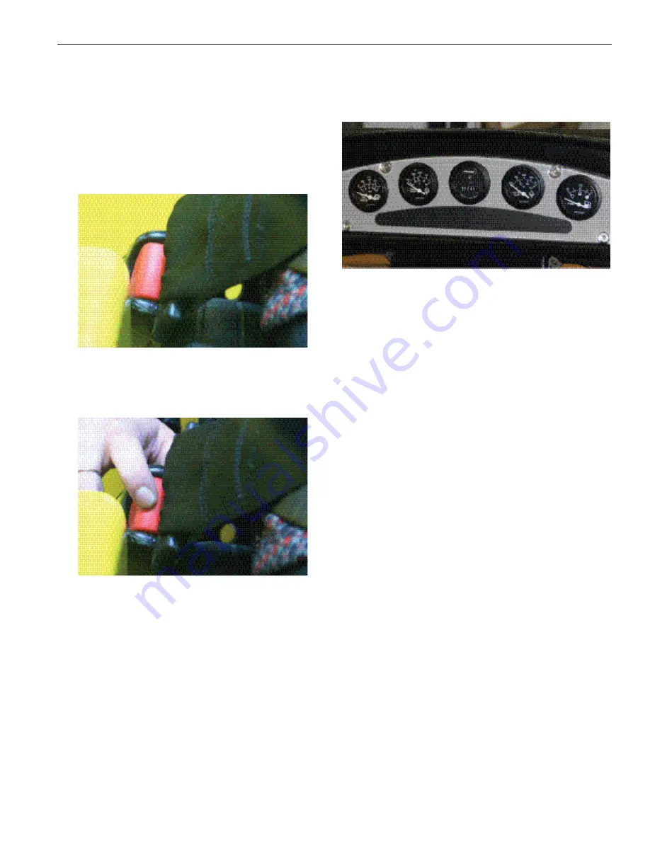
Instrument Panel

The instrument panel indicates the location of each 

standard and optional gauge, warning light and 

control.

Instrument Panel

figure 15. 

fuel Gauge

The fuel gauge indicates the level of diesel fuel in 

the fuel tank. The fuel gauge is electrically operated 

and registers only with the ignition switch in the ON 

or sTaRT position. 

Engine Coolant Temperature Gauge

This gauge indicates the temperature of the fluid 

in the engine cooling system. Normal coolant 

temperature for the Cummins QsB4.5 engine is 

160-194°f (70-90°C). NOTICE: Do not operate 

engine if coolant temperature exceeds 225°f 

(107°C).

Engine Hour Meter

Indicates the actual hours of engine operation. It 

records up to 9,999.9 hours and then restarts at 

zero. 

Transmission Temperature Gauge

This gauge indicates the temperature of the 

transmission oil. 

Normal Operating Range: 180-220°f (82-106°C)

Red Line Temperature: 250°f (121°C) 

Summary of Contents for Extendo 1032

Page 1: ...Operator s Manual PMOM 4021 736 744 936 944 1032 1144 1157 T944 T1157...

Page 2: ......

Page 3: ...Main Decal Kit LL 7858 11 0L1 10298 000 USE BOTH HANDS 12 FL 10561 SERVICE BRAKE 12 LL 1803 499 ACCUMULATOR 12 LL 4780 TRANSMISSION OIL FILL 12 LL 6163 MOTOR OIL 12 LL 7932 ASSEMBLED IN USA 12 LL 617...

Page 4: ...LL HAZARD 18 LL 6492 CARBON MONOXIDE 19 LL 6494 HIGH PRESSURE HYDRAULIC FLUID 19 LL 6497 UNTRAINED PERSONNEL 19 LL 7405 FASTEN SEAT BELT 20 LL 7406 FORWARD REVERSE 20 LL 7430 FALLING LOAD 20 LL 7474 C...

Page 5: ...Pre Startup Inspections 42 Walk Around Inspection 42 Check Engine Oil 42 Check Transmission Oil 42 Check Radiator Coolant Level 42 Check Hydraulic Fluid Level 43 Tires and Rims 44 Inspection for Leaks...

Page 6: ...le Pedal 52 Transmission Controls 52 Powershift Transmission Controls 52 Twist Grip Gear Shifter Directional Selector 52 Steering Wheel 52 Boom Features 52 Fork Leveling 52 Frame Tilt Sway 52 Gauges a...

Page 7: ...n Adjustment 102 Battery Replacement 102 Fuse Replacement 103 Engine Oil Change 103 Transmission Oil Change 104 Transmission Filter Element Replacement 104 Axle Lubricant Change 104 Required Scheduled...

Page 8: ...vi Extendo and Traverse Operation and Maintenance Manual 800 GO PETTIBONE Contents...

Page 9: ...e regulations or federal state and local laws Be sure the machine has the correct equipment according to these rules or laws Safety messages in this section point out situations that can be encountere...

Page 10: ...federal state provincial and local safety codes and regulations that apply to the job site A WARNIN A The safety messages that follow have WARNING level hazards These safety messages describe a hazard...

Page 11: ...ions or frayed insulation Repair or replace the loose or damaged parts Clean the entire machine to reduce risk of fire hazard before welding or using a torch on the machine Refer to the Advanced Maint...

Page 12: ...porting Check route to ensure sufficient clearances Check bridges for adequate weight limits Make sure the machine is securely tied down whenever transporting Chemical Burn Hazard Batteries contain su...

Page 13: ...178 l Safe Operating Practices Never allow anyone that is not trained or qualified to operate this machine Read and understand this operation manual before you operate or service this machine to ensur...

Page 14: ...nd Maintenance Manual 800 GO PETTIBONE 1 Pull Tab before welding Transmission Computer Disconnect before welding or any modifications 1 Figure 1 Transmission Computer 2 2 Disconnect this plug before w...

Page 15: ...ty 7 Extendo and Traverse Operation and Maintenance Manual 800 GO PETTIBONE Engine Computer Disconnect before welding or any modifications 1 Disconnect these plugs before welding Figure 1 Engine Compu...

Page 16: ...r the opening with tape to prevent air from spinning the turbocharger while vehicle is transported at highway speeds The turbochargers depend upon engine oil pressure to lubricate shaft bearings and m...

Page 17: ...the relief valve opens In some instances the consequences of increasing this setting have been serious The function of the relief valve is to provide a fuse action to protect the machine and the oper...

Page 18: ...ollow the instruction decals on the particular machine being operated Immediately replace any missing or damaged safety decal s and keep all safety decals clean and legible Contact an authorized deale...

Page 19: ...HYDRAULIC PRESSURE 1 LL 6463 MACHINE ROLL AWAY 1 LL 6465 ELECTROCUTION HAZARD 1 LL 6466 EXPLOSION HAZARD 1 LL 6467 HOT AND PRESSURIZED 3 LL 6468 NO RIDING 2 LL 6469 MOVING BELTS AND SPINNING BLADES 1...

Page 20: ...the dash beside the OSHA decal LL 1803 499 ACCUMULATOR Located under the hood cover on the accumulator LL 4780 TRANSMISSION OIL FILL Located on the cover on the right side of the machine and centered...

Page 21: ...the black plastic box behind the operator s seat LL 7700 WELDING AND MODIFICATION Located on the left side of the joystick console near the top and closest to the seat LL 7605 HYDRAULIC OIL ONLY Loca...

Page 22: ...on and Maintenance Manual 800 GO PETTIBONE LL 6456 COMBUSTIBLE AND FLAMMABLE FLUIDS Located on the top of the left side of tank LL 7984 SAFE OPERATION CHECK LIST Located on the front left frame of the...

Page 23: ...he top of the hydraulic tank closest to the cab LL 6463 MACHINE ROLL AWAY Located on the front left frame of the cab assembly above the welded handle LL 6465 ELECTROCUTION HAZARD Located on the right...

Page 24: ...RESSURIZED Located on the top rear cover next to the radiator cap LL 6468 NO RIDING One located on each side of fork frame LL 6469 MOVING BELTS AND SPINNING BLADES One located on the right side of the...

Page 25: ...ard tipover and falling boom decals LL 6471 HOT EXHAUST PIPE Located on the left side of the frame by the fuel tank and muffler LL 6472 PERSONAL INJURY Located on the left side of the dash between the...

Page 26: ...e of the frame in front of the cover LL 6480 PINCH POINT One located on the underside of each of the lift cylinders one inside the cab next to the cover and one beside each axle on the frame LL 6482 N...

Page 27: ...PETTIBONE LL 6492 CARBON MONOXIDE Located on the right side of the frame by the exhaust pipe LL 6494 HIGH PRESSURE HYDRAULIC FLUID Located on the left side of the frame inside the rear grill LL 6497...

Page 28: ...ed on the steering selector LL 7430 FALLING LOAD Located on the bottom side in the center of the boom LL 7474 CALIFORNIA PROPOSITION 65 WARNING Located on the center of the dash below the brake light...

Page 29: ...assembly on the back panel above the work platform decal LL 7537 UNCONTROLLED MACHINE Located on the left side of the cab assembly on the back panel below the safety instruction decal LL 7539 OSHA TRA...

Page 30: ...averse Operation and Maintenance Manual 800 GO PETTIBONE LL 7566 HYD OIL FILL PROCEDURE Located next to the sight gauge on the hydraulic tank LL 7599 PRE START MAINTENANCE Located on the front right f...

Page 31: ...and Traverse Operation and Maintenance Manual 800 GO PETTIBONE BL 9969 ANGLE INDICATOR Located on the left side of the boom 00L 09870 000 NO RIDING Centered on the top of the counterweight on the rea...

Page 32: ...h White Strip Part 15 Boom Fade with White Strip s FOR 4 MACHINES ONLY 45 5 4 0 3 0625 49 5 26 375 15 0 25 0 1 375 26 375 18 5 25 0 1 375 Part 0ETTIBONE LAG WITH GUIDES s USED WITH v BOOM FADE DECAL 4...

Page 33: ...ration and Maintenance Manual 800 GO PETTIBONE PART LL 7944 PETTIBONE FLAG WITH GUIDES L USED WITH 18 5 BOOM FADE DECAL ONLY 1157 T1157 1530 PART LL 7945 PETTIBONE FLAG WITH GUIDES R UDED WITH 18 5 BO...

Page 34: ...LACK 6INYL ECAL LL 7949 13 75 5 625 14 0 5 875 18 375 5 875 18 125 5 625 18 375 5 75 19 0 6 0 24 125 6 0 Part XTENDO LACK 6INYL ECAL Part XTENDO LACK 6INYL ECAL Part XTENDO LACK 6INYL ECAL Part LACK 6...

Page 35: ...SE 3ERIES LACK 6INYL 3TRIP 2 18 75 4 25 22 0 18 75 4 25 22 0 Part 4 LACK 6INYL 3TRIP Part 4 LACK 6INYL 3TRIP 17 8 4 25 20 43 17 8 4 25 20 43 LL 7956 Part XTENDO 3ERIES LACK 6INYL 3TRIP Part XTENDO 3ER...

Page 36: ...SSURE 1 FL 15591 DECAL LUBE CHART 736 744 2 LL 7946 744 MODEL DECAL 1 BL 10558 6 BOOM LENGTH 44FT 1 LL 7378 4 DECAL FR JSTK NEW EXT 1 LL 7378 2 DECAL REAR JSTK 1 LL 7942 PETTIBONE FLAG WITH GUIDES LH...

Page 37: ...LL 7949 1144 MODEL DECAL 1 BL 10558 6 BOOM LENGTH 44FT 1 LL 7378 4 DECAL FR JSTK NEW EXT 1 LL 7378 2 DECAL REAR JSTK 1 LL 7942 PETTIBONE FLAG WITH GUIDES LH 1 LL 7943 PETTIBONE FLAG WITH GUIDES RH 2...

Page 38: ...1032 2 LL 7948 1032 MODEL DECAL 1 LL 7890 BOOM LENGTH 32FT 1 LL 7378 17 DECAL FR JSTK BALER 1 LL 7378 2 DECAL REAR JSTK 1 LL 7942 PETTIBONE FLAG WITH GUIDES LH 1 LL 7943 PETTIBONE FLAG WITH GUIDES RH...

Page 39: ...E 1 FL 15556 DECAL LUBE CHART 944 1144 2 LL 7949 1144 MODEL DECAL 1 BL 10558 6 BOOM LENGTH 44FT 1 LL 7378 4 DECAL FR JSTK NEW EXT 1 LL 7378 2 DECAL REAR JSTK 1 LL 7942 PETTIBONE FLAG WITH GUIDES LH 1...

Page 40: ...Safety 32 Extendo and Traverse Operation and Maintenance Manual 800 GO PETTIBONE This Page Intentionally Left Blank...

Page 41: ...he time of printing Pettibone Traverse Lift LLC reserves the right to change specifications without prior notice in order to follow its policy of constantly striving to manufacture a better product wi...

Page 42: ...ance Manual 800 GO PETTIBONE Directional Reference All directional references right left front and rear used in this manual are as seen from the operator s seat Front of Machine 1 Left Side of Travers...

Page 43: ...tor compartment It contains the equipment model number serial number and gross vehicle weight GVW USE NUMBERS IN CORRESPONDENCE It is important that the model designation serial number and assembly pa...

Page 44: ...of the differential The axle identification plate contains the axle part number the serial number and the build date Axle Identification Plate Location Figure 5 Work Platform Reference Guide Pettibone...

Page 45: ...forklifts for the TRANSPORTATION of personnel RIDERS ARE NOT PERMITTED Only the operator is permitted in the cab during movement and placement of the forklift Although we cannot anticipate all field...

Page 46: ...maximum hydraulic pressure rating of the attachment is equal to or slightly greater than the machines main relief pressure setting which is the maximum available hydraulic pressure of this forklift N...

Page 47: ...nly if there is sufficient overhead clearance from all power lines A WARNIN A The safety messages that follow have WARNING level hazards These safety messages describe a hazardous situation which if n...

Page 48: ...transported in two or more moves If you cannot see over the load transport the load using reverse Do not make sudden stops while transporting loads Tip Hazard Do not attempt to raise or land loads th...

Page 49: ...and the function of each and every control before operating forklift Do not operate the forklift or handle loads in a reckless manner When driving do not make any sudden stops or turns Keep the forks...

Page 50: ...ns Engine Oil Dipstick Figure 6 Check Transmission Oil Start the engine and allow it to idle with the 1 transmission in NEUTRAL until the transmission reaches operating temperature Remove the transmis...

Page 51: ...d Remove fill plug and breather 2 Pour oil into fill plug hole 3 Note Oil must pass through return filters to get to the suction area of tank The sight glass level will lag behind oil level in filter...

Page 52: ...ture as indicated on the sight glass located on the side of the hydraulic tank Add hydraulic oil if necessary Entering the Operator s Compartment WARNING Fall Hazard Do not use the steering wheel or a...

Page 53: ...all times when driving this machine and will not be held responsible if the operator does not use the safety restraints available Instrument Panel The instrument panel indicates the location of each s...

Page 54: ...olant Temperature Fuel Gauge Warning Lights as pictured Figure 18 left to right Oil Pressure Low Battery Parking Brake Inclinometer This instrument shows the angle left or right of the machine frame r...

Page 55: ...is in axle lock mode boom above 25 with the parking brake on Rear Axle Lock Warning Light Figure 22 Rear Axle Restricted Mode This light glows orange when the vehicle is in axle restricted mode boom...

Page 56: ...f the charging system It is normal for light to come on at engine start up until electrical system reaches normal level Low Voltage Warning Light Figure 26 Engine Oil Pressure Warning Light This light...

Page 57: ...hydraulic controls are self centering to NEUTRAL Releasing handle returns them to their center NEUTRAL positions Both joysticks are located on a console to your right They control the following boom f...

Page 58: ...and holding the right button up to tilt the fork frame left and the right button down to tilt the fork frame right The left button up will tilt the fork frame forward and the left button down will ti...

Page 59: ...by the front joystick and the machine sway and traversing functions are controlled by the rear joystick The fork frame side tilt function is operated by pressing and holding the right button up to ti...

Page 60: ...en the cylinder extends and telescope inward when it retracts The forks achieve maximum lift height when the boom is fully raised and extended This telescopic action allows you to place loads at diffe...

Page 61: ...s NOTICE The forklift must be standing still when selecting any steering mode Equipment damage will occur if the mode is selected while the forklift is moving Determine the steering mode 3 a CRAB STEE...

Page 62: ...grip on the transmission selection lever to first gear 1 second gear 2 third gear 3 or fourth gear 4 Continue to hold the brake pedal down and release 7 the parking brake switch WARNING Uncontrolled M...

Page 63: ...Too much weight too far forward will cause the rear tires to rise off the ground This can be sensed very quickly by an operator and can be stopped before dangerously affecting the stability of the fo...

Page 64: ...FORKLIFT OPERATION 56 Extendo and Traverse Operation and Maintenance Manual 800 GO PETTIBONE Load Chart Kit 944 LL 7829...

Page 65: ...FORKLIFT OPERATION 57 Extendo and Traverse Operation and Maintenance Manual 800 GO PETTIBONE...

Page 66: ...FORKLIFT OPERATION 58 Extendo and Traverse Operation and Maintenance Manual 800 GO PETTIBONE Load Chart Kit T944 LL 7835...

Page 67: ...FORKLIFT OPERATION 59 Extendo and Traverse Operation and Maintenance Manual 800 GO PETTIBONE...

Page 68: ...FORKLIFT OPERATION 60 Extendo and Traverse Operation and Maintenance Manual 800 GO PETTIBONE...

Page 69: ...FORKLIFT OPERATION 61 Extendo and Traverse Operation and Maintenance Manual 800 GO PETTIBONE Load Chart Kit 944 LL 7836...

Page 70: ...FORKLIFT OPERATION 62 Extendo and Traverse Operation and Maintenance Manual 800 GO PETTIBONE...

Page 71: ...FORKLIFT OPERATION 63 Extendo and Traverse Operation and Maintenance Manual 800 GO PETTIBONE...

Page 72: ...FORKLIFT OPERATION 64 Extendo and Traverse Operation and Maintenance Manual 800 GO PETTIBONE Load Chart Kit 944 LL 7837...

Page 73: ...FORKLIFT OPERATION 65 Extendo and Traverse Operation and Maintenance Manual 800 GO PETTIBONE...

Page 74: ...FORKLIFT OPERATION 66 Extendo and Traverse Operation and Maintenance Manual 800 GO PETTIBONE Load Chart Kit 936 LL 7841...

Page 75: ...FORKLIFT OPERATION 67 Extendo and Traverse Operation and Maintenance Manual 800 GO PETTIBONE...

Page 76: ...FORKLIFT OPERATION 68 Extendo and Traverse Operation and Maintenance Manual 800 GO PETTIBONE Load Chart Kit T944 LL 7842...

Page 77: ...FORKLIFT OPERATION 69 Extendo and Traverse Operation and Maintenance Manual 800 GO PETTIBONE...

Page 78: ...FORKLIFT OPERATION 70 Extendo and Traverse Operation and Maintenance Manual 800 GO PETTIBONE...

Page 79: ...FORKLIFT OPERATION 71 Extendo and Traverse Operation and Maintenance Manual 800 GO PETTIBONE Load Chart Kit 1157 LL 7850...

Page 80: ...FORKLIFT OPERATION 72 Extendo and Traverse Operation and Maintenance Manual 800 GO PETTIBONE...

Page 81: ...FORKLIFT OPERATION 73 Extendo and Traverse Operation and Maintenance Manual 800 GO PETTIBONE...

Page 82: ...FORKLIFT OPERATION 74 Extendo and Traverse Operation and Maintenance Manual 800 GO PETTIBONE Load Chart Kit 1144 LL 7859...

Page 83: ...FORKLIFT OPERATION 75 Extendo and Traverse Operation and Maintenance Manual 800 GO PETTIBONE...

Page 84: ...FORKLIFT OPERATION 76 Extendo and Traverse Operation and Maintenance Manual 800 GO PETTIBONE Load Chart Kit 1144 LL 7860...

Page 85: ...FORKLIFT OPERATION 77 Extendo and Traverse Operation and Maintenance Manual 800 GO PETTIBONE...

Page 86: ...FORKLIFT OPERATION 78 Extendo and Traverse Operation and Maintenance Manual 800 GO PETTIBONE Load Chart Kit 736 LL 7861...

Page 87: ...FORKLIFT OPERATION 79 Extendo and Traverse Operation and Maintenance Manual 800 GO PETTIBONE...

Page 88: ...FORKLIFT OPERATION 80 Extendo and Traverse Operation and Maintenance Manual 800 GO PETTIBONE Load Chart Kit 744 LL 7862...

Page 89: ...FORKLIFT OPERATION 81 Extendo and Traverse Operation and Maintenance Manual 800 GO PETTIBONE...

Page 90: ...FORKLIFT OPERATION 82 Extendo and Traverse Operation and Maintenance Manual 800 GO PETTIBONE Load Chart Kit T 1157 LL 7886...

Page 91: ...FORKLIFT OPERATION 83 Extendo and Traverse Operation and Maintenance Manual 800 GO PETTIBONE...

Page 92: ...rive slowly in congested areas WARNING Crush Hazard Never attempt to drive across parallel to an excessively steep incline regardless of circumstances Inclines and Unstable Surfaces Driving on incline...

Page 93: ...1 3 minutes 5 Shut the engine off 6 Remove the ignition key from the switch 7 Unfasten seat belt 8 WARNING Fall Hazard Use hand rail and step Climb carefully from cab Block wheels of forklift if the...

Page 94: ...FORKLIFT OPERATION 86 Extendo and Traverse Operation and Maintenance Manual 800 GO PETTIBONE This Page Intentionally Left Blank...

Page 95: ...ntenance equipment is functioning properly and correctly installed Make sure that boom and attachments are grounded to avoid electrical shock A WARNIN A The safety messages that follow have WARNING le...

Page 96: ...containers Disconnect battery Handle fuel carefully Do not smoke while filling fuel tank or working near fuel Crush Hazard Lower boom to ground shut down machine to a zero energy state and remove key...

Page 97: ...t cold humidity etc you will need to service your machine more often Your experience may dictate a more severe servicing program Please read the complete text of the Operator s Manual carefully to rec...

Page 98: ...ls accordingly Units operated under extremely dusty conditions require the filters and breathers be serviced more often and monitored closely Damage caused by contamination is not covered by the warra...

Page 99: ...peration Check the gauges horn back up alarm seat belt and lighting for proper operation Fluids and Lubricants Refer to the Lubricants table when replacing oils fluids or filling fuel tank Filter Kits...

Page 100: ...Maintenance 92 Extendo and Traverse Operation and Maintenance Manual 800 GO PETTIBONE Grease Fitting Location Charts 7K Models Fixed Grease Fittings 7K Models Fixed Grease Fittings Figure 41...

Page 101: ...Maintenance 93 Extendo and Traverse Operation and Maintenance Manual 800 GO PETTIBONE 9K Models Fixed Grease Fittings 9K Models Fixed Grease Fittings Figure 42...

Page 102: ...Maintenance 94 Extendo and Traverse Operation and Maintenance Manual 800 GO PETTIBONE 9 11K Models Fixed Grease Fittings 9 11K Models Fixed Grease Fittings Figure 43...

Page 103: ...Maintenance 95 Extendo and Traverse Operation and Maintenance Manual 800 GO PETTIBONE 1157 Models Grease Fittings 1157 Models Grease Fittings Figure 44...

Page 104: ...Maintenance 96 Extendo and Traverse Operation and Maintenance Manual 800 GO PETTIBONE 7K Traversing Models 7K Traversing Models Figure 45...

Page 105: ...Maintenance 97 Extendo and Traverse Operation and Maintenance Manual 800 GO PETTIBONE 9K Traversing Models 9K Traversing Models Figure 46...

Page 106: ...Maintenance 98 Extendo and Traverse Operation and Maintenance Manual 800 GO PETTIBONE 11K Traversing Models 11K Traversing Models Figure 47...

Page 107: ...Elements At 500 1000 1500 and 2000 hours Working through the right side engine 1 compartment opening clean the filter head to prevent fuel contamination during filter element replacement Using a filte...

Page 108: ...housing Safety Element 1 Installing Safety Element Figure 52 Gently pat the sides of the primary element 5 to loosen dirt Do not tap the element against a hard surface CAUTION When using compressed a...

Page 109: ...p open the drain valve 2 and allow the radiator coolant to drain Position a drain pan beneath the engine coolant 3 drain plug located on the underside of the engine water inlet While holding a long sp...

Page 110: ...f batteries WARNING Chemical Burn Hazard Wear eye protection and rubber gloves Unfasten the hold down strap and remove the lid 1 from battery box Remove the nut from each battery post 2 Remove the bat...

Page 111: ...ummins distributor for information Operate the engine until the engine water 1 temperature reaches 140 F 60 C Position a drain pan beneath the engine oil pan 2 drain plug WARNING Burn Hazard Wear prot...

Page 112: ...sion filter located at the right front of the engine compartment Using a filter wrench remove the filter element 2 Apply a light coat of transmission fluid to the 3 surface of the element s gasket Ins...

Page 113: ...section specifies the maintenance schedule for each machine when operated under normal conditions Please refer to the Operation Under Severe Conditions section for the recommended adjustments to the...

Page 114: ...to the service manual Check the axle mounting bolt torque 300 ft lb Check the lug nut torque 310 ft lb Test the coolant protection level Refer to the engine manual Replace the hydraulic tank breather...

Page 115: ...ake system and filter Check the boom chain adjustments Refer to the service manual Check the lug nut torque 310 ft lb Test the coolant protection level Replace the hydraulic tank breather Service perf...

Page 116: ...eather Used in an extremely dusty environment 2 Used on more than one regular work shift per 3 day Used regularly on severe grades while loaded 4 Consistent service with high quality filters and fluid...

Page 117: ...Crankcase Breather X X X X C X X X C Alternator Belt X X X X X X X X X Transmission Fluid X CF X X CF X X X CF Transmission Filter X RF X X RF X X X RF Hydraulic Fluid X X X X CF X X X CF Hydraulic Fi...

Page 118: ...10 11k 14 x 24 16 81 psi 81 psi 7 9k 13 00 x 24 14 80 psi 80 psi Hydraulic Oil Hydraulic Oil Operating Temperature Range ISO Viscosity Grade 5 to 140 F 21 to 60 C 22 5 to 170 F 15 to 77 C 32 15 to 19...

Page 119: ......

Page 120: ...1100 Superior Ave Baraga MI 49908 Phone 1 800 Go Pettibone Fax 906 353 6325 www gopettibone com...

Reviews: