background image

24

Waste electrical products should not be disposed of with household waste.

 Please recycle where 

facilities exist. Do not dispose of electrical appliances as unsorted municipal waste, use separate collection 

facilities. Contact your local government for information regarding the collection systems available. If 

electrical appliances are disposed of in landfills or dumps, hazardous substances can leak into the ground-

water and get into the food chain, damaging your health and wellbeing. When replacing old appliances with 

new once, the retailer is legally obligated to take back your old appliance for disposal at least for free of 

charge. Disposal of discarded material shall be in accordance with local environmental regulations.

EXTENSION CORDS

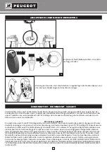
Only use extension cords with three conductors ending in two-pin plugs and sockets with two holes and an earth pin that 

are suited to the plug of the tool. When using a power tool at a considerable distance from the power source, use an exten

-

sion cord heavy enough to carry the current that the tool will draw. An undersized extension cord will cause a drop in line 

voltage, resulting in a loss of power and causing the motor to overheat. Use the chart provided below to determine the mini

-

mum wire size required in an extension cord. Only round jacketed extension listed by laboratories should be used.

Length of extension cord: up to 15 m

Wire size: 3 x 2.5 mm2

Before using an extension cord, inspect it for loose or exposed wires and cut or worn insulation. Repair or replace any dama

-

ged or worn cord immediately.

ELECTRICAL CONNECTIONS

Your machine has a precision built electric motor. It should be connected to a power supply that is 230 V, 50 Hz. If your tool 

does not operate when plugged into a socket, double-check the power supply characteristics.

The noise level of the machine is measured according to standards DIN EN ISO 3744: 1995-11 and DIN EN ISO 11203: 1996-07.

The values given are emission values calculated according to applicable standards and not values relating to use in the work

-

place. Although correlation between those different emission levels does exist, this cannot be reliably used to determine 

whether additional precautions are necessary. Factors with potential influence on the sound emission level in the workplace 

include the length of the period of work, the size of the room and any other sources of noise (e.g. number of machines opera

-

ting, other noisy work being carried out at the same time). Acceptable exposure levels may vary from one country to another. 

For all these reasons, we would advise users to wear equipment to protect their ears while using this machine.

Acoustic pressure level LpA:                  63,2 dB (A)

Uncertainties equal to 3 dB (A)

Earthing consists in connecting metal masses, that are liable to come accidentally in contact with the current due to faulty 

insulation in an electrical device, to an earth connection by means of a conductive wire. That earth connection, when used 

with a differential circuit breaker, prevents electrical incidents. The current flows directly into the earth and the power supply 

is automatically cut off.

Do not modify the supplied plug. If it cannot be put into the socket, have an appropriate socket installed by a qualified elec

-

trician.

If the earth conductor of a machine is incorrectly connected, this can lead to a risk of electric shock. The earth conductor is 

contained in green insulation with a yellow line. If the power cord needs to be repaired or replaced, do not connect the earth 

conductor to a live terminal.

Call in a qualified electrician or maintenance personnel if the earthing instructions are not fully understood or if in any 

doubt about the correct earthing of the tool.

If the power supply cable is damaged, it should be replaced by the manufacturer, the manufacturer’s after-sales department 

or similarly qualified person in order to avoid any danger. Do not use a tool if its power cord is damaged.

This tool is designed to be used with a circuit containing a power socket. It is also equipped with an earthing pin.

ENVIRONMENTAL PROTECTION

CONNECTING THE MACHINE – ELECTRICAL CONNECTIONS

NOISE INFORMATION

EARTHING INSTRUCTIONS

Summary of Contents for EnergyGrind-150TA

Page 1: ...TOURETS A MEULER SCHLEIFMASCHINEN BENCH GRINDERS MANUEL D UTILISATION BEDIENUNGSANLEITUNG OPERATING INSTRUCTIONS EnergyGrind 150TA EnergyGrind 150TBA EnergyGrind 150TMA ...
Page 2: ...2 SOMMAIRE P 3 11 P 12 20 P 21 29 The original instruction manual is in English F D GB ...

Page 3: ...ponse dans ce mode d emploi veuillez demander conseil à votre distributeur qui assistera professionnellement DIRECTIVES GENERALES DE SECURITE ET DU MANIEMENT DES MACHINES 1 Pour votre propre sécurité ne jamais mettre en marche une machine avant d avoir étudié son mode d emploi Il vous fait connaître la machine et son maniement vous familiarise avec ses possibilités et limites d exploita tion et vo...

Page 4: ...équilibre du corps 15 Maintenir la machine en bon état Garder les arêtes de coupe propres et bien acérées afin de pouvoir exploi ter toutes les capacités de la machine Respecter le mode d emploi lors du nettoyage le graissage et l échange des outils 16 Débrancher la fiche secteur avant de procéder aux travaux de maintenance ou à l échange d éléments tels que lames de scie forets et outils de coupe...

Page 5: ...L ajustement du dispositif de maintien des pièces doit être effectué progressivement de manière à compenser l usure de la meule En maintenant une distance aussi faible que possible entre le dis positif de maintien des pièces et la meule cette distance ne doit en aucun cas être supérieure à 2 mm 6 Raccorder s il y a lieu le dispositif collecteur de poussières prévu à cet effet 7 Contrôler régulière...

Page 6: ...SO 3744 1995 11 DIN EN ISO 11203 1996 07 Les valeurs citées sont des valeurs d émission calculées selon les normes en vigueur et non des valeurs liées à l utilisation sur le lieu de travail Bien qu il y ait une corrélation entre ces différents niveaux d émission il est impossible de tirer une quelconque conclusion sur des précautions supplémentaires à apporter Des facteurs ayant une influence pote...

Page 7: ...0TMA 430 W 430 W 430W 230V 50 Hz 230V 50 Hz 230V 50 Hz 120 min 1 2850 min 1 2850 min 1 2850 min 1 150 mm 150 mm 150 mm 200 mm 13 mm 13 mm 13 mm 20 mm 24 m s 24 m s 24 m s EnergyGrind 150TA EnergyGrind 150TBA SPECIFICATIONS IDENTIFICATION DE LA MACHINE 1 2 ...

Page 8: ...Porte outil ajustable 9 Brosse laitonnée 10 Meule à eau 11 Bac meule à eau 12 Vidange du bac à eau 13 Support réglable du bac à eau 14 Dressoir à meules avec support AVANT LE PREMIER DEMARRAGE 1 Fixez le touret sur un établi comme indiqué vis de fixation non fournies 2 Démontez les flasques des ou de la meule sèche 3 Utilisez une clé plate non fournie 4 Dégagez les meules de leur axe comme indiqué...

Page 9: ...et les 2 buvards 7 Fixez les écrans de protection comme indiqué Fig 9 8 Réglez les 2 supports en maintenant un écart de 2 mm entre leur rebord et la meule selon le schéma Fig 9 9 Faites tourner les meules avec la main et restez attentif à tout bruit anormal sans avoir branché l appareil 10 En cas de vibrations importantes pendant la mise en marche arrêtez immédiatement la machine et re démon tez l...

Page 10: ...che ou à droite de 0 à 45 3 Verrouillez le plateau tournant en revissant les deux bou lons de blocage Assurez vous que ces boulons soient bien serrés avant de remettre en marche la machine 12 13 DEMONTAGE DE LA MEULE A EAU Dévissez les vis A B C qui maintiennent le bac à eau après l avoir purgé au moyen du bouchon de vidange D DEMONTAGE DE LA BROSSE Dévissez les 6 vis A B C D E F qui maintiennent ...

Page 11: ...ntière confiance de PSP Outillage dans la qualité technique de ses produits la compagnie s engage à réparer ou à remplacer tout élément ou accessoire d un outil électrique Peugeot présentant un défaut dûment reconnu de matière ou de fabrication La garantie est d une durée de deux ans pour les articles de la marque Peugeot La ou les pièces présumées défectueuses doivent être renvoyées franco de por...

Page 12: ...ebrauch die die vorliegende Bedienungsanwei sung nicht beantworten kann wenden Sie sich bitte an Ihren Fachhändler zur Beratung ALLGEMEINE SICHERHEITSHINWEISE UND VORSCHRIFTEN ZUM GEBRAUCH DER MASCHINEN 1 Aus Gründen der persönlichen Sicherheit vor der Inbetriebnahme einer Maschine deren Bedienungsanwei sung lesen Sie informiert den Bediener über die Maschine und ihre Handhabung ihre Verwendungsmö...

Page 13: ...ht 15 Maschine immer in einwandfreiem Zustand halten Die Schneidflächen scharf und sauber halten um eine optimale Leistung der Maschine zu gewährleisten Die Betriebsanweisung für die Reinigung das Schmieren und den Wechsel von Anbaugeräten beachten 16 Maschine immer vom Netz trennen bevor Wartungsarbeiten oder der Wechsel von Maschinenteilen wie Sägeblatt Bohrer oder Schneidgerät usw erfolgen 17 N...

Page 14: ...betragen 5 Das Nachstellen der Werkstückspannvorrichtung ist ebenfalls im Zuge der Abnutzung der Schleifscheibe vorzunehmen Der Abstand zwischen der Werkstückspannvorrichtung und der Schleifscheibe ist so niedrig wie möglich zu halten und darf keinesfalls mehr als 2 mm betragen 6 Ggf die vorgesehene Staubabsaugung anschließen 7 In regelmäßigen Abständen aufgrund der Abnutzung der Spannvorrichtunge...

Page 15: ...hine wurde in Übereinstimmung mit folgenden Normen gemessen DIN EN ISO 3744 1995 11 DIN EN ISO 11203 1996 07 Bei den angegebenen Werten handelt es sich um gemäß den geltenden Normen berechnete Emissionspegel und nicht um mit der Ve rwendung der Maschine am Arbeitsplatz in Zusammenhang stehende Werte Zwar stehen Emissionspegel und Lärmbelastung im Zusam menhang jedoch können die Emissionswerte nich...

Page 16: ...rind 150TMA 430 W 430 W 430W 230V 50 Hz 230V 50 Hz 230V 50 Hz 120 min 1 2850 min 1 2850 min 1 2850 min 1 150 mm 150 mm 150 mm 200 mm 13 mm 13 mm 13 mm 20 mm 24 m s 24 m s 24 m s EnergyGrind 150TA EnergyGrind 150TBA SPEZIFIKATIONEN GERÄTEELEMENTE 1 2 ...

Page 17: ... 10 Nassschleifscheibe 11 Wasserbehälter 12 Ablassschraube des Wasserbehälters 13 Stellfuß des Behälters 14 Schleifscheibenabrichter mit Halterung VOR DER ERSTEN INBETRIEBNAHME 1 Die Schleifmaschine wie angegeben auf der Werkbank befestigen Schrauben nicht im Lieferumfang enthalten 2 Die Flansche der Trockenschleifscheibe n abbauen 3 Dazu einen Maulschlüssel verwenden nicht im Lieferumfang enthalt...

Page 18: ...Flansche und die 2 Pappflansche vergessen 7 Funkenschutzscheiben entsprechend Abb 9 fests chrauben 8 Entsprechend Abb 9 die beiden Halterungen einstellen dabei einen Abstand von 2 mm zwischen deren Rand und der Schleifscheibe einhalten 9 Die Schleifscheiben bei ausgeschaltetem Gerät per Hand drehen und auf jegliche anormale Geräusche ach ten 10 Treten beim Einschalten starke Vibrationen auf ist di...

Page 19: ...hteller durch Festschrauben der beiden Arretierbol zen sichern Vor der erneuten Inbetriebnahme der Maschine sicherstellen dass beide Bolzen fest angezogen sind 12 13 AUSBAUEN DER NASSSCHLEIFSCHEIBE Den Wasserbehälter mittels der Ablassschraube D entleeren und anschließend die Befestigungsschrauben A B C entfer nen AUSBAUEN DER BÜRSTE Die 6 Befestigungsschrauben A B C D E F des Flanschs ent fernen ...

Page 20: ...kte überzeugt und verpflichtet sich in diesem Sinne jegliches Bauteil oder Zubehör eines elektrischen Geräts der Marke Peugeot zu reparieren bzw zu ersetzen das einen ordnungsgemäß festgestellten Materia loder Fertigungsfehler aufweist Wir gewährleisten 2 Jahre Garantie auf sämtliche Artikel der Marke Peugeot Das bzw die fehlerhafte n Bauteil e sind versandkostenfrei an das Werk oder eines der PSP...

Page 21: ...d cannot find the answer in these instructions please contact your distributor who will be glad to offer you professional advice GENERAL SAFETY AND MACHINE USE GUIDELINES 1 For your own safety never start up a machine before carefully reading its instructions for use The instruc tions will provide information about the machine and how it is to be used make you familiar with its possibili ties and ...

Page 22: ...machine in good condition Keep the cutting edges clean and sharp in order to make the most of all the capacities of the machine Follow the instructions for use when cleaning lubricating and replacing tools 16 Disconnect the mains plug before carrying out any maintenance work or before replacing components such as saw blades drill bits cutting tools etc 17 Only use the recommended accessories and f...

Page 23: ...r than 2 mm 5 Adjust the work piece holding device gradually so as to make up for grinding wheel wear The dis tance between the work piece holding device and the wheel must be as small as possible and in no case greater than 2 mm 6 If necessary connect the dust collecting system provided 7 Regularly check the limit thickness value which may be crossed due to wearing of the work piece holding devic...

Page 24: ...g to applicable standards and not values relating to use in the work place Although correlation between those different emission levels does exist this cannot be reliably used to determine whether additional precautions are necessary Factors with potential influence on the sound emission level in the workplace include the length of the period of work the size of the room and any other sources of n...

Page 25: ... 150TMA 430 W 430 W 430W 230V 50 Hz 230V 50 Hz 230V 50 Hz 120 min 1 2850 min 1 2850 min 1 2850 min 1 150 mm 150 mm 150 mm 200 mm 13 mm 13 mm 13 mm 20 mm 24 m s 24 m s 24 m s EnergyGrind 150TA EnergyGrind 150TBA SPECIFICATIONS MACHINE IDENTIFICATION 1 2 ...

Page 26: ...wire wheel brush 10 Wet grinding wheel 11 Wet grinding wheel tank 12 Tank drain 13 Adjustable water tank support 14 Wheel dressing tool with support BEFORE INITIAL STARTING UP 1 Secure the grinder to a work bench as shown fastening screws not supplied 2 Remove the flanges from the dry grinding wheel or wheels 3 Use an open ended spanner not supplied 4 Take the wheels off their spindles as shown in...

Page 27: ...o pads 7 Fasten the eye shields as shown in Fig 9 8 Adjust the two supports so that the distance between their edge and the grinding wheel is 2 mm as shown in Fig 9 9 Turn the wheel with your hand and check that it does not make any strange noises before connecting the ma chine 10 If the machine vibrates significantly when it is started up stop it immediately take off the grinding wheels and check...

Page 28: ...r right hand graduations from 0 to 45 3 Lock the rotating base using the two locking bolts Make sure that the bolts are securely fastened before starting up the machine once again 12 13 REMOVING THE WET GRINDING WHEEL Unscrew the screws A B C holding the water tank after first draining it via drain plug D REMOVING THE WIRE BRUSH WHEEL Unscrew the six screws A B C D E F holding the flange Proceed a...

Page 29: ...ged for shipment Because of our confidence in our engineering quality PSP Tooling agrees to repair or replace any part or parts of Peugeot power tools and accessories which examination proves to be defective in workmanship or material The warranty period for Peugeot brand is two years Any alleged defective part or parts must be returned prepaid to PSP Tooling or one of the service centres The guar...

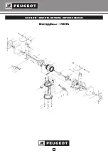
Page 30: ...30 EnergyGrind 150TA VUE ECLATEE ERSATZTEIL ZEICHNUNG EXPLODED DIAGRAM ...

Page 31: ...31 EnergyGrind 150TBA ...

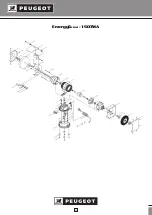
Page 32: ...32 EnergyGrind 150TMA ...

Page 33: ...arateurs agréés En aucun cas durant la période de garantie le matériel ne devra être démonté 1 Scope of the warranty The warranty shall only apply to manufac turing defects or material defects We are obliged to exchange or repair parts that are identified as being unusable 2 Lifetime warranty The warranty shall be valid for 24 months from the delivery date of the equipment to the user invoice or t...

Reviews: