ELECTRICITY
13
Reproduction ou traduction, même partielle, interdite sans autorisation écrite de Peugeot Motocycles
ELECTRICITY
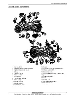
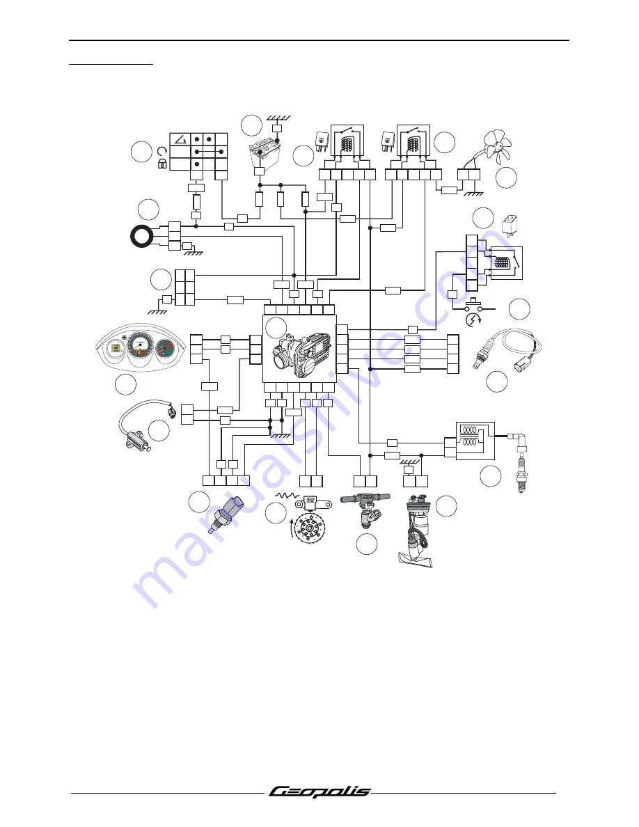
4 stroke indirect injection system functional diagram
1.
Injection ECU.
2.
Engine speed and position sensor.
3.
Petrol injector.
4.
Petrol pump.
5.
Ignition coil.
6.
Lambda sensor.
7.
Starter motor switch.
8.
Starter motor relay.
9.
Cooling fan.
10. Fan relay.
11. Injection relay.
12. Battery.
13. Ignition switch.
14. Transponder antenna.
15. Diagnostic plug.
16. Instrument panel.
17. Kickstand switch.
18. Engine temperature sensor.
12V - 25A
2
1
3
4
5
12V - 25A
1
2
3
4
5
2
1
3
4
5
1 2
6
3
OFF
ON
11
7
8
-
U
P
P
E
R
L
E
V
E
L
LO
W
E
R
L
E
V
E
L
VE
B1
A1
A3
VE
6
5
4
3
2
18
17
16
15
14
13
12
11
10
9
8
7
2 1
2
1
22
21
11
4
15 14
13
9
26 12
1
17
18
8
24
20
7
16
5 6
1
R
1
2
4
3
1
2
3
2
1
1
2
30A
F1
15A
F6
10A
F2
15A
F4
VE
VE
VE
VE
JN
BC
NR
NR
NR
RG
RG
VI
VE-NR
RG-BA
BA-BE
VE-NR
VE-NR
VE-JN
BE-NR
BA-VE
VI-BA
BE-NR
GR-RG
RG-NR
VI-NR
VE-NR
GR-RG
MR-BA
BA-NR
1
2
+
BE
BA
VE
VE
VE
RG MR OR
VI
NR
Km
100
60
50
Km/h
40
30
20
10
70
80
90
10
0
120
140
160
80
60
40
80
40
120
20
0
M
Hrs
PEUGEOT
Summary of Contents for Geopolis 250
Page 1: ...Direction commerciale Animation technique réseau WORKSHOP MANUAL ...
Page 50: ......
Page 51: ......


