30
pewag levo hook
EN
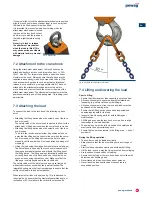
Lowering the load:
• Lower the load slowly and bring it into a stable and safe
position.
• Only open the swivel hook when the load has been secured
against tilting, falling, sliding etc.
• By opening the swivel hook, parts of the lifting device (lifting
eye, shackle etc.) that was used to lift the load may fall down.
Always lower the levo hook as far down as possible before
opening it. Open the swivel hook in such a way that neither
persons nor objects may be hit by falling parts.
• The maximum load for opening the hook is approx. 20 kg –
depending on the lifting device.
8. Procedure in case of
accidents or faults
There are four possible reasons why the status display can
light up:
1. The device is malfunctioning
2. The test interval for the device has been exceeded
3. Pairing mode (see section 5.4)
4. If the hook is turned on
In case of malfunctioning, try acknowledging the fault memory
by deactivating the device using the on/off button. Wait 10
seconds before reactivating the levo hook. If the status display
no longer lights up, the error was temporary. Continue using
the device as normal.
If the status display lights up again immediately or after a short
period, the device must be inspected by pewag austria GmbH
or by an authorised pewag dealer and repaired as required.
If the swivel hook is blocked or stuck to the load, do not use
excessive violence to release it. This may damage the safety
catch or the swivel hook. Lower the load and resolve the fault
using manual force. If the swivel hook, casing or attachment
mechanism show signs of deformation (e.g. due to overloading)
or other unusual events, the device must be removed from
service and handed to a competent person for inspection or
repair (see chapter 9.9 Regular inspections and repairs).
9. Cleaning, maintenance,
regular inspections
We recommend keeping the original packaging of the
pewag levo hook throughout its entire lifespan in case of
returns!
9.1 Cleaning
In case of heavy soiling, the pewag levo hook should be
cleaned as follows:
• Outer surface of the casing, attachment mechanism and
swivel hook: using a cloth and, where required, a non-
aggressive fat solvent.
• Plastic parts (e.g. battery cover, on/off button): with a dry
cloth
• Battery compartment or inner part of the battery: with a dry
cloth
Do not use high-pressure cleaners, steam blasters or similar
devices for cleaning.
9.2 Maintenance & repair
The levo hook must be checked for visible damage and/or dirt
prior to each use.
The following faults may be rectified by a competent person in
accordance with this manual:
• Cleaning in case of heavy soiling
• Missing or defect safety catch (e.g. broken spring)
• Safety catch counter piece
• Damaged or missing flaps or bolts on the attachment
mechanism
• Exchanging the battery unit
• Exchanging the battery in the levo remote radio control
With all other faults, the pewag levo hook must be removed
from service and handed for inspection and repair to pewag
austria GmbH or an authorised pewag dealer (also see chapter
9.9 Regular inspections and repairs).
Always use original
pewag spare parts!
The pewag levo hook may no longer be used if any of the
following apply:
• Cracked or deformed casing, attachment mechanism or
swivel hook
• Missing or damaged safety catch kit or parts thereof (e.g.
broken spring)
• Blocked swivel hook during opening or closing
• Damaged battery cells
• Missing or illegible identification plate
• Loose or missing other parts such as covers or screws
• Heavy soiling or corrosion
Under no circumstances are users permitted to bend, weld or
otherwise repair parts that are deformed, cracked or broken!
Remove the battery prior to each repair measure to avoid
accidental activation of the swivel hook.
9.3 Exchanging the safety catch set
If parts of the safety catch set are missing or defective (e.g.
broken spring), users may replace them as follows:
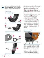
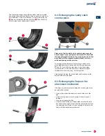
Fold the safety catch
1
down fully towards the inner part of the
swivel hook and loosen the safety screw
2
using an Allen key
as shown in fig. 14. Slide out the axle
3
. You may now remove
the safety catch
1
incl. the spring
4
from the hook (fig. 15).
Remove the spring.
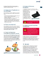
When assembling the set, follow these steps in reverse order,
paying particular attention to the following points:
• When inserting the spring
4
in the safety latch
1
, the spring
leg running parallel to the axial direction
5
must be inserted
into the drill hole on the inside of the safety latch (fig. 16)
• The other spring leg, i.e. the one running transversal to the
axial direction
6
must be inserted into the drill hole in the
hook
7
(fig. 17)
• Use a small amount of medium-strength threadlock for the
safety screw
2
(e.g. Loctite type 243)

