April 2019
4
Translation of original operating manual for lifting points PLZW pewag winner profilift zeta
• The attached lifting device must be free to move in the ring.
• Keep lifting points clean and dry. Treat lifting points
carefully even after use. Do not let lifting points drop to the
floor as this may damage the thread or other parts.
• The base material of the object to which the lifting points
are to be attached must be strong enough to absorb the
forces that occur without deformations (proof of safety).
• Always choose lifting points with the correct dimension
acc. to the load capacity table, depending on the size of
the load and the constellation of the lifting devices.
• Choose the constellation of lifting points in such a way that
symmetrical loading is assured and the centre of the load
is positioned under the lifting point(s).
• When choosing your constellation, check that there is no
risk of improper loading due to any of the following factors:
- direction of pull is obstructed
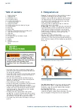
- direction of pull is not within the indicated area (fig.1)
• Any severe conditions (see restrictions on use) must be
taken into account.
• Always take into account the user and assembly
instructions of the lifting devices used and, where
applicable, also those of the load to be lifted.
• For custom-made designs: Take into account the additional
information provided and the specifications on the
customer‘s drawings (where applicable).
• The condition as delivered must not be altered.
Surface treatments that may damage the material, welding,
heat treatments etc. are not permitted.
• The length of the thread may not be shortened.
3.2 Protective measures to be taken
by the user
Always take into account the restrictions on use and the
maximum load capacity of the lifting points used. Always
wear safety gloves when attaching the lifting device.
Align the lifting point in the expected direction of pull and
leave the hazard area before lifting the load. Slightly tension
the chain sling and check that the lifting devices are correctly
fitted to the lifting points and that all lifting points are correctly
aligned in the direction of pull before lifting the load.
Keep a sufficient safety
distance during the
lifting operation and
ensure that the load has been lowered safely
before removing the lifting device. Do not
overload lifting points! Falling loads may cause
injury and/or death!
3.3 Remaining risks
Overloading caused by non-compliance with the
maximum load capacity or adverse environmental factors
(temperature...). Incorrect assembly of the lifting points may
lead to failure, as may the use of non-authorised or damaged
parts of the attached lifting device.
3.4 Mounting
• The screw-on surface must be level and have at least the
diameter of the contact surface of the lifting point. The
sufficiently deep, threaded hole must be at the centre of the
contact surface, at a right angle.
It must be possible to insert the screw fully
(with blind holes).
• Clean the threaded hole prior to each use and check for
damage.
• The minimum screw penetration values are:
1 x M for steel (Rm > 360N/mm²)
1.25 x M for cast steel
2 x M for aluminium
(M = thread size, e.g. M20 = 20 mm)
• Additional elements (such as washers) between the lifting
point and the load are not permitted.
• Prior to each use, ensure that the lifting point is fully screwed
in and that the contact surface is flush with the load.
• For one-off transport, it is admissible to tighten the screw
by hand using a spanner.
• If the lifting point is intended to remain permanently
attached to the load, it must be tightened with an
appropriate tool with a torque as listed in table 1. If
necessary (i.e. in case of vibrations), the thread must be
secured with a liquid threadlock (e.g. Loctite).
• After assembly, ensure that there is no risk of incorrect
loading by aligning the lifting point in the expected load
direction by moving the ring.
3.5 Dismounting
To remove the lifting point, unscrew it with a suitable tool.
Store the lifting point as described in „Storage“. Take
appropriate measures to protect the thread on the load from
damage and dirt.
3.6 Attaching closed lifting devices
to the lifting point
As this lifting point
is dismountable,
the screw is relatively
easy to remove. Always store the lifting point
carefully and correctly after use (e.g. attached to
the ring).
This lifting point may be dismounted by the user in such a
way that a closed lifting device (e.g. rope loop, eye sling
hooks) may be fitted to the ring. This process does not
require any tools and may only be performed when the lifting
point is not attached to a load.
Always wear safety gloves and work at a table so you do not
lose any parts.


