background image


6

7.8 

Connect a microampmeter or voltmeter to the Primary Safety Control as directed in the PSC 
manufacturer’s instruction bulletin to determine flame detection system values.  The meter is normally 
connected in series with the (SENSE) terminal on the S8680 series control. 

 
7.9 

With the main and leak test cocks and pilot cock in 

OFF 

position, turn on the gas cock at meter.  Check to 

make certain that the pressure upstream of main and pilot cocks does not exceed 14” W.C.  (1/2 PSIG) – 
unless special valve train components suitably rated have been furnished (Refer to Burner Specification 
Sheet).  If pressure is acceptable, proceed to next step. 

 
7.10 

Pilot Ignition 


Next check the operation of the gas pilot system.  This is a very important part of the start up 
procedure.


A. 

Before attempting burner start up make certain that you are familiar with the operation of the 
Primary Safety Control and other components being used on this specific application.  Refer to 
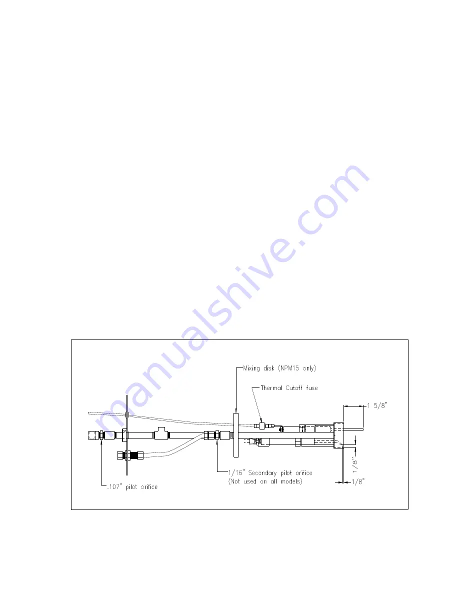
Fig. 5 and 5A for pilot spark gap dimensions. 

 
B. 

To prepare the pilot for proper operation, it is essential that appropriate adjustments be made on 
the burner air inlet damper and to the pilot gas pressure.  Initial air damper opening should be 
approximately 1/8 inch open for low high low or modulating type models.  On fixed rate burners 
the air damper may have been factory set to a predetermined opening.  The pilot pressure 
needed will be affected by the damper position.  Typical pilot pressure is 0.5” W.C.  higher than 
the static air pressure measured on the pilot during pre-purge for natural and propane gas.   
 

C. 

In many instances, pilot problems relate to gas pressures that are too high or too low, 
causing the pilot gas mixture to be just outside of the ignition range.  The optimum pilot 
pressure should be determined by adjusting the pilot regulator and finding the minimum 
and maximum pressure that the pilot lights.  Then, set the pilot regulator where the 
pressure is in the middle of these two pressures.


Figure 5.  Pilot Assembly – Flame Rod Type – Natural Gas/LP Gas  - NPM15 – 24 Volt 


Summary of Contents for NPM15-10-120

Page 1: ...ed NOVA PREMIX INSTALLATION AND OPERATION MANUAL THE POWER TO MANAGE ENERGY 2001 South 21st Street Parsons Kansas 67357 Telephone 620 421 0480 Fax 620 421 0948 Web Site www powerflame com E mail CSD powerflame com NPM 12 04 ...

Page 2: ...1 1 1 1 4 1 1 4 1 1 2 Blower Wheel Size 7 x 3 7 x 3 7 x 3 8 1 4 x 1 1 2 9 1 8 x 2 1 2 Blower Motor HP 1 4 1 4 1 2 1 2 1 Motor Voltage 120 60 Hz 120 60 Hz 120 60 Hz 120 60 Hz 120 60Hz Control Voltage 24 V 120 V 120 V 120 V 120 V Inlet Pressure To Main Shut off Cock Inches W C Min Max 6 8 14 0 6 7 14 0 7 3 14 0 8 2 14 0 11 6 14 0 3 ACCEPTANCE PROCEDURE Uncrate burner carefully and check all parts re...

Page 3: ...a heat exchanger end wall or in the base of the boiler see Figures 1 and 2 The opening for the burner blast tube should not be less than 6 8 or 10 inches in diameter depending on the burner model to allow easy removal of the burner The gap between the boiler opening and the blast tube should be sealed with non asbestos high temperature rope or Ka O Wool Where a new or replacement combustion chambe...

Page 4: ...Gas Installation Code CAN CGA B149 1 or Propane Installation Code CGA B 149 2 5 2 Size the main gas line in accordance with Table 2 The figures shown are for straight lengths of pipe at 0 2 W C pressure drop which is considered normal for low pressure systems Note that fittings such as elbows and tees will add to the pipe pressure drop Table 2 Gas Piping Pressure Drop Data EQUIVALENT LENGTH OF STR...

Page 5: ...nating clear of windows or fresh air intakes Outside termination of vent should have a screen to prevent insects from building nests in vent pipe The vent should terminate in a manner which will preclude the possibility of water dirt or other foreign matter from entering the line Refer to state or local codes for proper venting requirements 5 8 Test gas lines for leaks using a soap solution Your l...

Page 6: ...sed as reference in burner start up and service 7 2 Check boiler water level if applicable and all safety interlocks 7 3 Lay out combustion test equipment see Section 8 4 7 4 Attach gas pressure gauge or manometer to upstream side of main gas cock 0 35 W C and to orifice pressure tap 0 10 W C as well as to pilot gas pressure test tee tapping 0 10 W C Note On burners using the combination gas valve...

Page 7: ...on this specific application Refer to Fig 5 and 5A for pilot spark gap dimensions B To prepare the pilot for proper operation it is essential that appropriate adjustments be made on the burner air inlet damper and to the pilot gas pressure Initial air damper opening should be approximately 1 8 inch open for low high low or modulating type models On fixed rate burners the air damper may have been f...

Page 8: ...rong steady signal reading Connect a DC voltmeter or microampmeter to the flame safeguard control as appropriate to determine flame detection system signal values Refer to Table 3 B Adjust the pilot regulator to obtain approximately 0 5 to 1 0 W C pressure at the pilot test port Note This pressure varies depending on the damper opening burner model The actual pilot gas pressures will typically be ...

Page 9: ...and other combustion values at the proper firing input rates Generally accepted values for natural gas are 8 1 2 to 10 CO2 or 5 1 2 to 3 O2 Equivalent CO2 readings on propane gas are 10 to 11 1 2 CO2 or 5 1 2 to 3 1 2 O2 It is important that the CO carbon monoxide level is checked and held at 0 or minimum typically under 100ppm or 0 01 Check with the local gas utility and any other authorities hav...

Page 10: ...ient gas consumption premature wear of burner and heat exchanger components uncontrolled combustion 8 3 Approximate gas flow rates and corresponding pressures are shown in Table 4 for natural gas and propane gas These rates pressures represent approximately 5 excess 02 at 0 0 W C furnace pressure Since the amount of excess air will affect the actual manifold pressure rate verification of the exact...

Page 11: ...ot open 4 Shut off knob on combination valve not turned On 5 Defective main valve 9 4 Occasional lockouts for no apparent reason 1 Re check micoamp readings If insufficient check gas pressure and air damper setting Check electrode setting If flame signal is low flame rod may have to be re positioned 2 Check ignition cable and electrode porcelain for damage or breaks which could cause short 3 Check...

Page 12: ...rner in Off Position W C Low Fire Low Fire W C High Fire High Fire W C Gas Pressure at Firing Head Low Fire W C High Fire W C Gas Pressure at Pilot Test Tee W C Flame Signal Readings D C Volts Micro Amps Pilot Low Fire High Fire CO2 or O2 Specify Low Fire High Fire CO Low Fire PPM High Fire PPM Input Rate Low Fire BTU HR High Fire BTU HR Overfire Draft Low Fire W C High Fire W C NOx Corrected to 3...

Page 13: ...st Checked For Proper Operation Of Yes No Yes No Low water cut off Barometric damper High water cut off Boiler room combustion air Flame safeguard control ignition failure ventilation provision correct Flame safeguard control main flame failure Oil tank vent system correct Burner air flow switch All oil lines checked for leaks Induced draft fan controls All gas lines checked for leaks Over fire dr...

Reviews: