background image

  S    c     h     w     e     i     ß     t     e     c     h     n     o     l     o     g     i     e               G    m     b     H  


  K a r l - B r ö g e r - St r . 1 0     D E- 3 6 3 0 4   A l s f e l d     T e l : + 4 9 - 6 6 3 1 - 9 6 5 2 - 0     F a x : + 4 9 - 6 6 3 1 - 9 6 5 2 - 5 2  


Barcode Electro Fusion Control Box

Barcode Electro Fusion Control Box

Barcode Electro Fusion Control Box

Barcode Electro Fusion Control Box    


PF 

PF 

PF 

PF –

– polymatic

 polymatic

 polymatic

 polymatic    

PF 

PF 

PF 

PF –

– polymatic light

 polymatic light

 polymatic light

 polymatic light    


PF-Schweißtechnologie GmbH – Karl-Bröger-Str. 10 – DE-36304 Alsfeld 

Tel.: +49-(0)6631-9652-0     Fax.: +49-(0)6631-9652-52 


Rev.: 2004-001-GB


Summary of Contents for Polymatic

Page 1: ...on Control Box Barcode Electro Fusion Control Box Barcode Electro Fusion Control Box Barcode Electro Fusion Control Box PF PF PF PF polymatic polymatic polymatic polymatic PF PF PF PF polymatic light...

Page 2: ...Rev 2004 001 DE 2...

Page 3: ...ontrols and Plugs 9 5 Power Connection 10 5 1 Generator suitability 11 6 Starting a welding process 11 6 1 Preparation 11 6 2 Welding with the Barcode Mode 13 6 3 FUSAMATIC Mode 15 7 Other Functions 1...

Page 4: ...eeps the right to make technical changes at the device which are not directly included into the present instructions manual 1 1 Maintenance periods Please note that the bought product is a technically...

Page 5: ...on voltage fusion time with temperature correction if applicable resistance and resistance tolerance FUSAMATIC System By reading out the reference resistance in the connector pins of the FUSAMATIC Fit...

Page 6: ...play Display 4 x 20 Characters alphanum background lighting 4 x 20 Zeichen alphanumerisch Hintergrundbeleuchtung Dimension Abmessungen 440mm x 380mm x 320mm Monitoring Functions berwachungsfunktionen...

Page 7: ...Light Duty Cycle at 100 60 and 30 Polymatic Polymatic Light 10 20 30 40 50 60 70 80 90 100 1500W 2000W 2500W 3000W 3500W 4000W Duty Cycle ISO 12176 2 at Uref 36V 10 20 30 40 50 60 70 80 90 100 1500W...

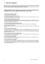
Page 8: ...5 Store up your device safely Unused machines should be kept in a dry and locked room inaccessible for children and unauthorized people 6 Use permitted accessories only Do only use accessories especia...

Page 9: ...Rev 2004 001 DE 9 4 Controls and Plugs 1 Display 2 START green 3 STOP red 4 5 6 7 4 Power Switch 5 Welding Cable 6 Cable Holder 7 Power Supply Cable...

Page 10: ...3600W Caution 110V Control Units shall not be used at 230V power supply and vice versa When operating on a electric distributor or the main power supply of nominal 230V a min 16 Amps slow fuse compri...

Page 11: ...ut Power 20 75 mm 2kW 90 160 mm 3 2kW 180 710mm 4 5kW mechanically controlled 5kW electronically controlled For generators with insufficient control performance or voltage control it has to be selecte...

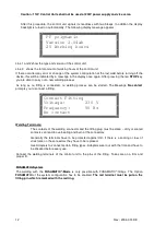
Page 12: ...d no welding process can be started The Message No contact prompts you to connect a fitting Connect Fitting Voltage 230 V Frequency 50 Hz No contact Welding Terminals The contacts of the welding conne...

Page 13: ...or invalid the error will be displayed and indicated by a bleep You read in the barcode by using the scanner or reading pen Using the reading pen Place the tip of the reading pen left or right beside...

Page 14: ...he measured resistance At the left and right the borders of the resistance range given in the barcode is shown Row 2 shows the nominal welding time Row 3 shows the report number of the faulty process...

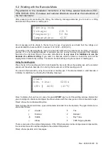
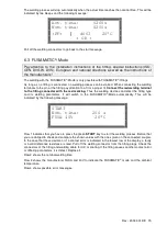
Page 15: ...nector with the red marking Thus the welding device can detect the fitting type and its welding parameters It will switch to the FUSAMATIC Mode automatically This will be indicated by the following me...

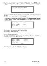
Page 16: ...tomatically To avoid danger for your health do not touch the fitting or cables during the welding process The display shows the actual and nominal welding time Act time 0099 s Nom time 0200 s PLAS 40V...

Page 17: ...u item START short Moves the cursor upwards STOP short Moves the cursor downwards START 3 sec Selects the marked menu item STOP 3 sec Cancels the function menu 7 2 Adjusting the display contrast By se...

Page 18: ...the system configuration menu the display will show a list of language indicators GB SE ES The indicators stand for GB English SE Swedish ES Spanish IT Italian DK Danish PT Portuguese DE German FR Fr...

Page 19: ...lding cable has to be equipped by a welding terminal with detection tip You have to use welding terminals that are delivered by PF only 5 Screw the new welding terminal tight into the brass contact an...

Page 20: ...nts the total amount of working hours summed up fusion times After ten seconds the above shown display will disappear If there occurred any error or change of the system configuration at the last weld...

Page 21: ...cool down for about 45 min Emergency cut out Welding was interrupted by pressing the STOP key Welding is faulty Frequency error Input frequency out of working range 40 70Hz Check Generator Input volta...

Page 22: ...e Clean the contacts Use an other fitting Service The recommended service interval of 200 working hours is exceeded The device has to be checked by an authorized service point The device is still usab...

Page 23: ...Rev 2004 001 DE 23 9 Conformity Declaration...

Page 24: ...Rev 2004 001 DE 24...

Reviews: