background image

Adjustment

11 - 19

11

.05.17

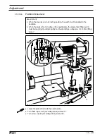
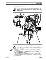
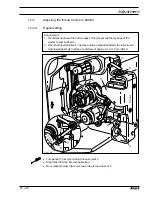
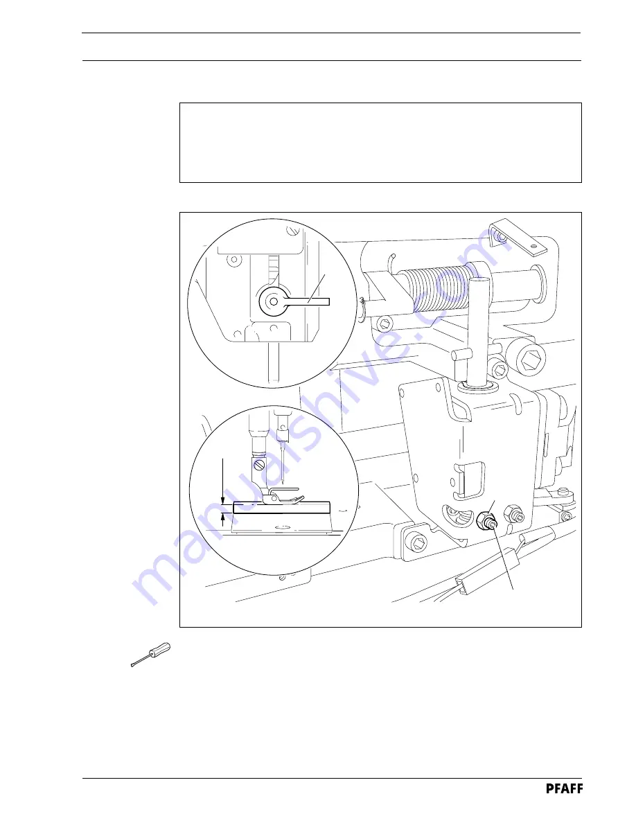
Knee lever stop

Requirement

When the knee lever is fully actuated,

1. the presser foot must be raised approx. 

9 mm

 (or approx. 

13 mm

 for a large needle bar

stroke) above the needle plate, and

2. lever 

3

 must swing down automatically.

Loosen nut 

1

 and unscrew screw 

2

 a few turns.

Raise the presser foot and slide a 

9 mm

 (for small needle bar stroke) or 

13 mm

 (for large

needle bar stroke) thick spacer under the presser foot.

Swing down lever 

3

Move the knee lever until it is fully actuated. The presser foot must remain on the

spacer.

Now turn screw 

2

 as far as it will go.

Turn screw 

2

 a half turn back and tighten nut 

1

.

1

2

Fig. 11 - 18

3

9 or 13 mm

Summary of Contents for 1051

Page 1: ... 1053 1181 1183 296 12 18 453 002 Betriebsanleitung engl 03 01 This instruction manual applies to machines from the following serial numbers onwards PFAFF 1051 2232500 PFAFF 1053 2232222 PFAFF 1181 2232501 PFAFF 1183 2232224 ...

Page 2: ...horization and with written reference to the source G M PFAFF KAISERSLAUTERN INDUSTRIEMASCHINEN AG Postfach 3020 D 67653 Kaiserslautern Königstr 154 D 67655 Kaiserslautern Editing Illustrations HAAS Publikationen GmbH D 53840 Troisdorf This Instruction Manual is valid for all models and subclasses listed in the chapter Specifications ...

Page 3: ...ackaging 5 1 5 04 Storage 5 1 6 Explanation of the symbols 6 1 7 Controls 7 1 7 01 On off switch 7 1 7 02 Keys on the machine head 7 1 7 03 Pedal 7 2 7 04 Lever for lifting the presser foot 7 2 7 05 Feed regulator disk 7 3 7 06 Reverse feed lever 7 3 7 07 Knee lever 7 4 7 08 Thread trimmer 731 01 7 4 7 09 Switch for thread wiper 909 04 7 5 8 Mounting and commissioning the machine 8 1 8 01 Mounting...

Page 4: ...04 Neutral position of the needle feed only on PFAFF 1051 and 1181 11 6 11 05 05 Bottom feed lifting motion 11 7 11 05 06 Bottom feed dog height 11 8 11 05 07 Feed dog motion of bottom feed dog 11 9 11 05 08 Feeding motion of needle feed only on PFAFF 1051 and 1181 11 10 11 05 09 Needle in needle hole center only on PFAFF 1053 and 1183 11 11 11 05 10 Needle to needle hole centre on PFAFF 1051 and ...

Page 5: ...read catcher 11 30 11 07 03 Knife position 11 31 11 07 04 Front point of reversal of the thread catcher 11 32 11 07 05 Manual trimming check 11 33 11 07 06 Thread tension release 11 34 11 07 07 Readjusting the control cam 11 35 11 08 Adjusting the thread wiper 909 04 11 36 11 08 01 Thread wiper movement 11 36 11 08 02 Thread wiper position 11 37 11 09 Adjusting the automatic presser foot lift 910 ...

Page 6: ...ng sewing tools e g needle roller presser needle plate and bobbin when threading the machine when leaving the machine unattended and during maintenance work the machine is to be separated from the power supply by switching off the On Off switch or by removing the plug from the mains Everyday maintenance work is only to be carried out by appropriately trained personnel Repairs and special maintenan...

Page 7: ...onnel is to be instructed as to the safety equipment of the machine and regarding safe work methods It is the duty of the user to only operate the machine in perfect running order It is the obligation of the user to ensure that none of the safety mechanisms are removed or deactivated It is the obligation of the user to ensure that only authorized persons operate and work on the machine Further inf...

Page 8: ...hanges in the machine which may limit its safety 1 05 02 Specialist personnel Specialist personnel are persons with a specialist education in the fields of electrics electronics and mechanics They are responsible for the lubrication maintenance repair and adjustment of the machine The specialist personnel is obliged to observe the following points and must always observe the Notes on Safety in the...

Page 9: ...ed accidentally If an external motor is used do not operate the machine without the belt guards 4 and 5 Danger of injury by the drive belt 1 06 Danger A working area of 1 meter is to be kept free both in front of and behind the machine while it is in operation so that it is always easily accessible Never reach into the sewing area while sewing Danger of injury by the needle Never leave objects on ...

Page 10: ...ee single needle ultra high speed seamer with drop feed These machines are used in the industry for sewing lockstitch seams Any and all uses of this machine which have not been approved of by the manufacturer are considered to be inappropriate The manufacturer cannot be held liable for any damage caused by the inappropriate use of the machine The appropriate use of the machine includes the observa...

Page 11: ... 4 5 mm Version CN 6 0 mm Max speed PFAFF 1051 1053 Version A and B 4000 spm Max speed PFAFF 1181 1183 Version A and B 5500 spm Version CN 4200 spm Needle bar stroke 30 or 36 mm Power connection Operating voltage 190 240 V 50 60 Hz single phase Max input 400 VA Fuse 1 x 16 A inert Ambient noise levels Workplace noise level at corresponding speeds noise measurement according to DIN 45 635 48 A 1 IS...

Page 12: ... materials Version B for sewing medium materials Version C for sewing medium heavy materials Work aids Subclass 731 01 edge trimmer Subclass 900 24 thread trimmer Subclass 909 04 thread wiper Subclass 910 06 automatic foot lift Subclass 911 37 automatic back tacking mechanism ...

Page 13: ... various plastics The electrical equipment consists of plastics and copper The machine is to be disposed of in accordance with the locally valid environmental protection regulations If necessary a specialist is to be commissioned Special care is to be taken that parts soiled with lubricants are separately disposed of in accordance with the locally valid pollution control regulations ...

Page 14: ...he customer s premises or to the individual locations of use Make sure that the machines are always transported upright 5 03 Disposal of the packaging The packaging of these machines consists of paper cardboard and VCE fiber The proper disposal of the packaging is the responsibility of the customer 5 04 Storage The machine can be stored for up to 6 months if not in use During this time it should b...

Page 15: ...f this Instruction Manual certain tasks or important pieces of information are accentuated by symbols The symbols used have the following meanings Note information Cleaning care Lubrication greasing Servicing repairing adjustment maintenance only to be carried out by specialist personnel ...

Page 16: ...inish back tack Key 3 when sewing is interrupted the needle can either be raised or lowered as required 7 Controls 7 01 On Off switch Turn the machine on off by pressing the On Off switch 1 With the buttons 2 the parameters such as back tacking function raising the presser foot needle position at sewing stop etc can be pre selected also see the Motor Instruction Manual Fig 7 01 Fig 7 02 1 2 2 3 1 ...

Page 17: ...al 0 Machine stop 1 Sew 2 Raise presser foot for machines with 910 06 3 Trim thread for machines with 900 24 Fig 7 03 0 1 2 3 7 04 Lever for lifting the presser foot The presser foot is raised by turning lever 1 Fig 7 04 1 ...

Page 18: ... 05 Feed regulator disk The stitch length can be set by simultaneously applying pressure to disk 1 and turning it to the desired setting 7 06 Reverse feed lever For reverse sewing press lever 1 Fig 7 06 1 Fig 7 05 1 ...

Page 19: ...e knee lever 1 in the direction of the arrow the presser foot is raised Fig 7 07 1 Fig 7 08 1 7 08 Thread trimmer 731 01 Do not touch the running motor Danger of injury By pressing or raising key 1 1 1 1 1 the edge trimmer is switched on or off ...

Page 20: ...Controls 7 5 I Fig 7 09 7 09 Switch for thread wiper 909 04 By moving switch 1 the thread wiper can be switched on or off Position l aggregate is on Position 0 aggregate is off 1 ...

Page 21: ...fficiently sturdy even during sewing operations 8 01 Mounting The necessary electricity supply must be available at the machine s location Also a stable and horizontal surface as well as adequate lighting are required at the location Depending on the type of table the method of packaging used may require that the table top be lowered for transport The following is a description of how to adjust th...

Page 22: ...r is shown in Fig 8 02 If another motor is used carry out this step according to the instructions in the motor instruction manual Fig 8 02 8 01 03 Mounting the upper V belt guard This step is eliminated for integrated sewing motors Break out the belt guard case 1 at the points marked by the arrows Fasten belt guard 2 in holes 3 Attach belt guard 4 to the machine case with screws 5 1 2 2 cm 3 3 Fig...

Page 23: ...or pulley and the V belt run freely Tighten screws 2 A quick motor is shown in Fig 8 04 If another motor is used carry out this step according to the instructions in the motor instruction manual Fig 8 04 8 01 05 Mounting the spool holder Mount the spool holder as shown in Fig 8 05 Insert the spool holder into the hole in the table top and fasten it with the nuts enclosed Fig 8 05 2 2 1 ...

Page 24: ...dge of the table top cutout see Fig 8 0 6 Insert the machine in the table top After loosening screws 3 push switch 2 forwards until it touches the plate 1 In this position tighten screws 3 If the machine is tilted backwards switch 2 prevents the motor from starting accidentally ERROR 92 appears on display 4 After the machine has been placed in an upright position switch off the motor with switch 5...

Page 25: ...ne s motor can be operated with the available electricity supply and that it is connected properly If not the machine must not be operated 8 03 Switching the machine on off Switch the machine on see Chapter 7 01 On Off switch 8 01 07 Connecting the plug connections and earth cable Fig 8 08 Connect all plugs coming from the machine as labelled in the control box Attach earth cables 1 and 2 on the r...

Page 26: ... 0 0 2 9 8 0 2 9 8 0 2 1 7 17 4 1 5 0 2 4 1 5 0 2 12 85 40 71 5 0 1 33 9 6 0 3 28 0 2 8 5 50 1 5 1 5 4 5 4 5 1 5 1 5 5 1 8 3 0 R 1 0 2 x R 1 9 2 x 0 5 R 3 0 R 3 0 R 10 R 10 R 10 R 1 0 R 10 R 1 0 R 10 R 1 0 R 1 9 2 x 0 5 180 5 0 5 1 20 R 1 9 0 5 R 1 0 2 x R 1 9 0 5 3 0 45 A Y Y M 2 1 Z M 2 1 8 04 Table top cutout ...

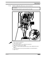
Page 27: ... mains or switching off the On Off switch 9 01 Inserting the needle Switch off the machine Danger of injury due to unintentional starting of the machine Only use needle system DBx1 or 134R depending on machine equipment Observe sticker on machine Raise needle bar Loosen screw 1 and insert needle 3 until you feel it stop The long needle groove must be aligned in the direction of the machine head Ti...

Page 28: ...ls up during sewing If the machine is only run for bobbin winding without sewing a hook base must be fitted in the hook Otherwise a jammed thread may damage the hook The tension of the thread on bobbin 1 can be adjusted with knurled screw 4 The bobbin winder stops automatically when bobbin 1 is full If the thread is wound unevenly Loosen nut 5 Turn thread guide 6 accordingly Tighten nut 5 Fig 9 02...

Page 29: ...obbin case base Return the machine to its upright position using both hands Danger of injury by crushing between the machine and the table top Fig 9 03 9 04 Inserting the bobbin case Adjusting the bobbin thread tension Insert the bobbin into the bobbin case Pass the thread through the slot under the spring according to Fig 9 04 Pass the thread through the notch Adjust the thread tension by turning...

Page 30: ...needle thread Adjusting the needle thread tension Switch off the machine Danger of injury due to unintentional starting of the machine Thread the machine as shown in Fig 9 05 Adjust the needle thread tension by turning disk 1 Fig 9 05 1 ...

Page 31: ...t operation If the machine is operated more than this shorter intervals are recommended 10 01 Cleaning the machine Switch off the machine Danger of injury due to unintentional starting of the machine Tilt back the machine Clean the hook and hook compartment daily more often if in continuous operation Return the machine to its upright position using both hands Danger of injury by crushing between t...

Page 32: ...ervoir tilt back the machine and let it rest on the sewing head support Fill oil through hole 1 into the reservoir 2 up to the level of the front edge see arrow Return the machine to its upright position using both hands Danger of injury by crushing between the machine and the table top Only use oil with a mean viscosity of 10 0 mm2 s at 40 C and a density of 0 847 g cm3 at 15 C We recommend PFAFF...

Page 33: ...o be removed and replaced for checks and adjustment work are not mentioned here The screws and nuts in brackets are attachments of machine parts which are to be loosened before making the adjustment and tightened again after the adjustment has been carried out 11 02 Tools gauges and other accessories for adjusting 1 set of screwdrivers with blade widths from 2 to 10 mm 1 set of wrenches with jaw w...

Page 34: ...ar is roughly in required position Insert blocking pin 1 in hole Turn balance wheel slightly back and forth until blocking pin engages crank 2 Needle bar position 0 6 mm past t d c Set needle bar roughly at required position Place adjustment gauge 3 onto pins 4 and 5 making sure right side is used for 30 or 36 mm needle bar stroke Needle bar position 0 6 mm past b d c Set needle bar roughly at req...

Page 35: ...f toothed belt 2 has been removed Requirement When the needle bar position is 0 6 mm above the BDC the marks on the machine housing 3 and toothed belt wheel 1 must be flush with each other Set needle bar at 0 6 mm past b d c Turn toothed belt sprocket 1 according to Requirement and push on toothed belt 2 Fig 11 02 57 42a 3 4 1 2 ...

Page 36: ...m above BDC the mark on the needle bar 1 must be flush with the bottom edge of the needle bar frame 3 Fig 11 03 Set needle bar at 1 8 mm past b d c and block machine with blocking pin see Chapter 11 04 Checking and adjusting aids Move needle bar 1 screw 2 without turning it according to the requirement 2 1 3 ...

Page 37: ...ment At stitch length setting 0 cranks 1 and 3 must be flush and the feed dog must not make any feeding motion when the balance wheel is turned Raise the presser foot and set the stitch length to 0 Turn crank 1 screw 2 according to the requirement Fig 11 04 3 2 1 ...

Page 38: ...f the needle feed only on PFAFF 1051 and 1181 Requirement At stitch length setting 0 the needle bar must not make any feeding motion when the balance wheel is turned Fig 11 05 Set stitch length 0 Turn crank 1 screw 2 according to Requirement 1 2 ...

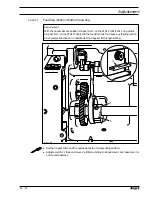
Page 39: ...t on control cam 3 must be parallel with the bedplate at needle bar position t d c on all machines types Set stitch length 0 and set needle bar at required position Turn eccentric 1 screws 2 according to Requirement 1 Adjust control cam 3 screws 4 according to Requirement 2 Set needle bar at t d c and adjust control cam 3 screw 4 according to Requirement On machines without thread trimmer 900 24 c...

Page 40: ...e length Set stitch length at 0 and feed dog 1 at its highest position Raise the presser foot Place feed dog adjustment gauge 2 on the needle plate cutout with the arrow in sewing direction so that it is flush with the front edge and lower the presser foot onto it Adjust feed bar 3 screws 4 according to Requirement 1 Loosen screws 5 and 6 Adjust feed bar 3 or eccentric 7 according to Requirement 2...

Page 41: ...on 0 6 past t d c on the PFAFF 1053 1183 the feed dog must not make any feeding motion when reverse feed lever 3 is operated at the longest stitch length setting 1 2 3 Fig 11 08 Set the longest stitch and the needle bar at the corresponding position Adjust eccentric 1 loosen screws 2 a little according to Requirement but make sure it is not moved sideways ...

Page 42: ...eccentric 1 screws 2 until the adjustment pin 3 locks into place 11 05 08 Feeding motion of needle feed only on PFAFF 1051 and 1181 Requirement When the longest stitch length is set and the needle bar is positioned 0 6 mm past b d c the needle should not move when the reverse feed key 4 is operated ...

Page 43: ...t the needle in the needle hole Loosen screws 1 2 and 3 Move the needle bar frame 4 according to the requirement Tighten screw 2 and turn screw 3 slightly Via screw 1 bring the retracted guide bolt to the eye of the needle bar frame 4 and tighten it Turn the handwheel a few times to prevent distortion to the needle bar frame 4 Tighten screw 3 3 2 1 4 Fig 11 10 ...

Page 44: ...AFF 1051 and PFAFF 1181 Requirement The needle must enter excatly in the centre of the needle hole Set stitch length 0 Set the needle in the needle hole by turning the balance wheel Turn needle bar frame 1 screws 2 and 3 according to Requirement Fig 11 11 1 3 2 ...

Page 45: ...drop feed only on PFAFF 1051 and PFAFF 1181 Requirement At the longest stitch length setting the needle and feed dog must move by the same stroke when the balance wheel is turned Fig 11 12 Set the longest stitch Turn crank 1 screws 2 according to Requirement 1 2 ...

Page 46: ...he same time the slot in the hook shaft bearing 1 see arrow must be par allel to the bedplate and pointing opposite to the direction of sewing 2 There must be a slight amount of play between the gears 3 and 5 Align hook shaft bearing 1 screw 2 according to requirement 1 Slide gear 3 screws 4 on to the shaft according to requirement 2 4 3 1 5 Fig 11 13 14 5 mm 6 2 1 ...

Page 47: ...quirement 1 Check requirement 2 If necessary move centrifugal disk 1 11 05 13 Hook lubrication only for PFAFF 1181 and 1183 Requirement 1 The centrifugal disk 1 must be positioned 1 5 mm in front of the oil ring 3 2 When the machine is running at full speed after approx 10 seconds a mark should be made by a fine stripe of oil on the strip of paper placed over the needle plate cutout Fig 11 14 2 1 ...

Page 48: ...f the needle eye must be 0 8 mm below the hook point 3 Between the projection of the bobbin case position finger 4 and the bottom of the retaining groove there should be a distance of 0 5 mm Using the adjustment pin position the needle bar at 1 8 mm after BDC Adjust the hook according to requirement 1 Tighten screw 1 Move needle bar 2 screw 3 without turning it according to requirement 2 Align bob...

Page 49: ...op is at its largest when going around the hook the thread check spring must have moved by approx 1 mm Turn thread tension 1 screw 2 according to requirement 1 Turn thread tension 3 screw 4 according to requirement 2 Due to technical sewing reasons it may be necessary to deviate from the spring stroke indicated above Move the slack thread regulator 3 screw 4 toward the more thread or toward the le...

Page 50: ... 2 When the presser foot is resting on the needle plate the presser bar lifting lever 6 must be touching the circlip 8 lightly and be at a distance of approx 1 mm from lifting piece 7 Lower the presser foot onto the needle plate Turn shaft 1 screws 2 according to Requirement 1 Turn screw 3 nut 4 according to Requirement 2 Fig 11 17 5 1 4 3 8 6 7 1 mm 2 ...

Page 51: ...ing down automatically Loosen nut 1 and unscrew screw 2 a few turns Raise the presser foot and slide a 9 mm for small needle bar stroke or 13 mm for large needle bar stroke thick spacer under the presser foot Swing down lever 3 Move the knee lever until it is fully actuated The presser foot must remain on the spacer Now turn screw 2 as far as it will go Turn screw 2 a half turn back and tighten nu...

Page 52: ...h the bobbin winder off the friction wheel 5 must not be driven by the drive wheel 1 3 The bobbin winder must turn off automatically when the thread level is approx 1 mm from the edge of the bobbin Move drive wheel 1 screws 2 in accordance with requirement 1 and 2 Move bolt 3 screw 4 in accordance with requirement 3 Fig 11 19 3 4 ...

Page 53: ...th which can be selected can be limited mechanically When using Version A and B part sets the maximum adjustable stitch length must not be larger than 4 5 mm Set the desired maximum stitch length with regulator disk 1 Move crank 2 screws 3 down against stop 4 2 4 3 Fig 11 20 1 ...

Page 54: ...ent 11 22 11 05 20 Presser foot pressure Requirement The material must be fed reliably In the process pressure marks on the material must not be made Fig 11 21 Turn screw 1 in accordance with the requirement 1 ...

Page 55: ... 3 screws 2 as far as possible toward large needle bar stroke or toward small needle bar stroke Adjust needle height see chapter 11 05 02 Preadjusting the needle height and or chapter 11 05 14 Needle rise hook to needle clearance needle height and bobbin case position finger 11 05 21 Modifying the needle bar stroke The needle bar stroke is preset in the factory according to requirement The needle ...

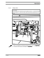
Page 56: ... the edge trimmer 731 01 11 06 01 Zero position of the knife Requirement With the edge trimmer switched off the knife should not move when the balance wheel is turned Turn crank 1 screw 2 according to the requirement 1 2 2 1 Fig 11 23 ...

Page 57: ...irement Turn eccentric 1 two screws 2 according to the requirement requirement requirement requirement requirement 11 06 02 Cutting motion Requirement With the edge trimmer switched on and the needle bar at its t d c on the PFAFF 1053 and 1183 or at its b d c on the PFAFF 1051 and 1181 the knife should be at the top of its stroke 1 2 Fig 11 24 ...

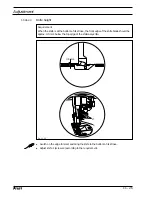
Page 58: ...ottom of its stroke Adjust knife 1 screws 2 according to the requirement 11 06 03 Knife height Requirement When the knife is at the bottom of its stroke the front edge of the knife blade should be approx 0 5 mm below the top edge of the stationary knife 0 5 mm 1 2 Fig 11 25 ...

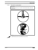
Page 59: ...t knife bracket 1 screw 2 according to the requirement 11 06 04 Knife position in sewing direction Requirement When the needle is at its b d c the centre of the knife blade should be positioned at needle centre 1 2 Fig 11 26 ...

Page 60: ...28 Adjust knife bracket 1 screw 2 according to the requirement 11 06 05 Knife position crosswise to sewing direction Requirement The knife should be resting on the stationary knife 3 with light pressure 1 2 Fig 11 27 ...

Page 61: ... washer 5 must be 96 mm 2 When the thread trimmer is in resting position magnet retracted the roller lever 6 must rest against bolt 7 and be at a distance of approx 0 1 mm from roller 8 Turn plunger 1 nut 2 according to requirement 1 Bring thread trimmer into resting position Move magnet holder 3 screws 4 according to requirement 2 Fig 11 28 1 96 mm 4 3 5 4 2 6 0 1 m m 8 7 ...

Page 62: ...d catcher 5 must be horizontal It must not graze anything when it is operating Remove knife 1 screw 2 Move needle bar to its BDC Loosen stop 3 screws 4 Position thread catcher 5 screw 6 manually in front of the needle Align thread catcher 5 screws 7 according to the requirements For further adjustments leave knife 1 removed and stop 3 loosened Fig 11 29 7 5 4 3 1 2 5 6 ...

Page 63: ...he right edge of the thread catcher see arrow Bring the needle bar to BDC Slide knife 1 under the locking tab and align according to requirement 1 Tighten screw 2 lightly Adjust thread catcher carrier 3 by hand until the wedge point in the thread catcher is positioned just in front of the cutting edge of the knife Align knife 1 according to requirement 2 and tighten screw 2 Fig 11 30 4 mm 1 1 2 3 ...

Page 64: ...her 5 is at its front point of reversal the rear edge of the thread catcher cutout must be positioned 1 mm before the bobbin case position finger 6 Swing roller level 1 into the lowest point of the control cam 2 Move thread catcher carrier 3 screw 4 according to the requirement 3 4 2 1 Fig 11 31 6 5 1 mm ...

Page 65: ... front point of reversal Double the thread and insert into catcher cutout Carry out trimming operation manually If the threads are not cut according to the requirement align thread catcher 1 screws 2 with knife 3 accordingly Move stop 4 against thread catcher 1 and tighten screws 5 Check chapter 11 06 02 Lateral alignment of the thread catcher and readjust if necessary 2 1 5 4 3 1 Fig 11 32 ...

Page 66: ...e magnet lift should be 1 5 mm 2 When the magnet 5 is operated by hand there should be a distance of at least 0 5 mm between the tension discs 6 Adjust disc 1 nuts 2 according to the requirement Adjust screw 3 nut 4 according to the requirement Fig 11 33 0 5 mm 6 3 4 5 2 1 ...

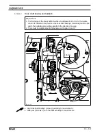
Page 67: ...rought from the highest point of the control cam 2 and moved against bolt 4 basic position Switch on machine and sew a few stitches Trigger cutting operation Check to see if the thread was cut cleanly and roller level 1 is in basic position If necessary turn control cam 2 screws 3 according to the requirement 2 3 4 1 Fig 11 34 ...

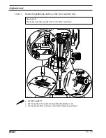
Page 68: ...d wiper 5 is to move under the needle point and clear it by approx 1 mm when the engaging solenoid 2 is operated Bring the take up lever to TDC Loosen screws 1 Push thread wiper 2 parallel to the bedplate to the very top and tighten screws 1 slightly Turn bracket 3 screw 4 according to requirement 1 Move thread wiper 2 parallel to the bedplate according to requirement 2 Tighten screws 1 Fig 11 35 ...

Page 69: ...ead wiper 5 must be approx 1 1 5 mm to the right of the needle and 2 The thread wiper 5 must be approx 2 mm in front of the needle in its foremost position Fig 11 36 5 1 1 5 mm 2 mm 5 1 2 4 3 Slide bracket 1 screw 2 without turning it on the shaft according to requirement 1 Turn rod 3 nut 4 according to requirement 2 ...

Page 70: ...matic presser foot lift is operated the clearance between the presser foot and the needle plate must be 9 mm 9 mm 9 mm 9 mm 9 mm for a small needle bar stroke and 13 mm 13 mm 13 mm 13 mm 13 mm for a large needle bar stroke Move magnet 1 screw 2 according to the requirement Fig 11 37 2 1 9 or 13 mm ...

Page 71: ...ting the back tacking mechanism 911 37 Regel When the longest stitch length is set the reverse feed control switch 3 operated and the plunger extended lever 1 should not touch the bed plate Adjust lever 1 screw 2 according to the requirement 3 ...

Page 72: ... 91 99 137 187 15 2x 99 137 186 05 99 137 189 05 4x 99 137 188 15 99 137 190 05 3x 91 262 377 91 99 137 192 05 99 137 194 05 99 137 193 05 99 137 191 05 PFAFF 1181 1183 91 262 437 05 12 Wearing parts This list indicates the most important wearing parts You can request a detailed parts list for the complete machine under parts number 296 12 18 344 91 701 179 15 2x 91 100 296 25 2x 11 330 958 15 Sub...

Page 73: ...91 171 042 05 11 108 087 15 91 262 235 15 91 171 853 15 91 108 222 15 91 262 184 15 11 108 084 15 2x Subclass Trimming margin Partnumber 731 01 8 11 A 5 0 91 069 595 04 002 731 01 8 11 B 3 5 91 169 395 04 002 731 01 8 11 B 4 0 7 0 91 069 595 04 002 ...

Page 74: ...IEMASCHINEN AG Postfach 3020 D 67653 Kaiserslautern Königstr 154 D 67655 Kaiserslautern Telefon 0631 200 0 Telefax 0631 17202 E Mail info pfaff industrial com Gedruckt in der BRD Printed in Germany Imprimé en R F A Impreso en la R F A ...

Reviews: