Adjustment
21
Fig. 13 - 16
13
.05.06
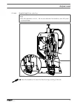
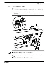
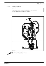
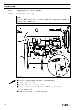
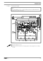
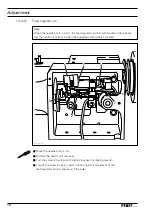
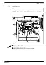
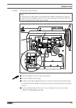
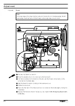
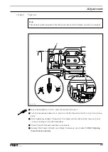
Front turning point of thread catcher
Rule
When the thread catcher
3
is in the front turning point, the rear edge of the thread catch-
er cutout should still be
1 mm
above the front edge of the bobbin case position finger
6.
O
Move the needle bar to b.d.c.
O
Activate the field core
1
so that the feed regulator pin
2
drops into the cam track.
O
Move the thread catcher
3
to its front turning point by turning the handwheel (direction
of rotation).
O
Set the thread catcher
3
according to the
rule
by turning the thread catcher carrier
4
(screws
5).
1
2
5
3
4
6
1 mm
Summary of Contents for 333-712/02
Page 29: ...Notes...

