12 - 50
Adjustment
3
3
1
2
4
6
Fig. 12 - 49
81-100
5
12
.06.03
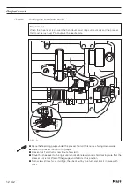
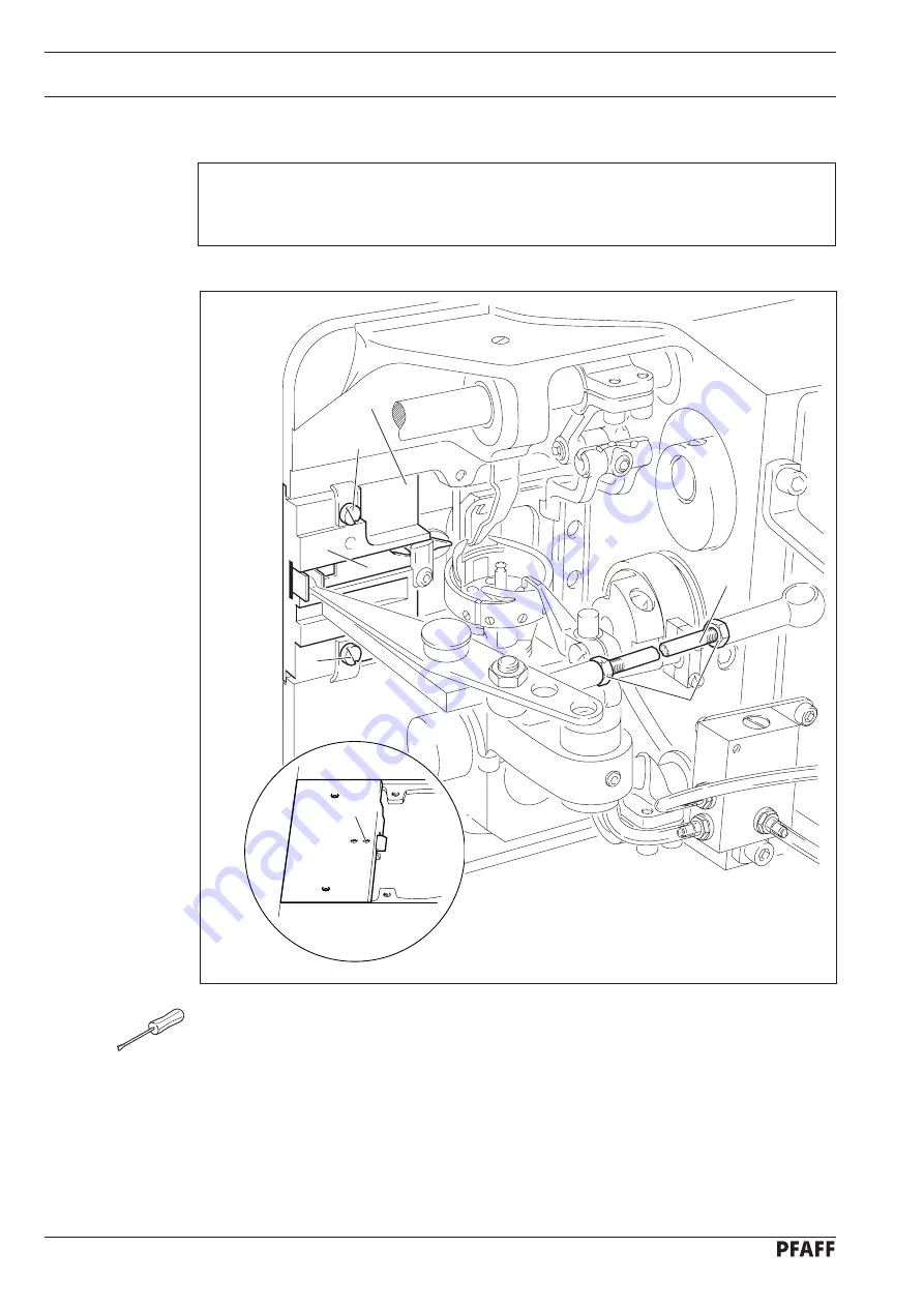
Position of the thread catcher and cutting test
Requirement
When the thread trimmer is in its neutral position, the edge of thread catcher
6
should be
flush with the edge of the mounting plate
4
.
●
Turn linkage rod
1
(nuts
2
, left and right thread) in accordance with the
requirement.
●
During the cutting test, remove linkage rod
1
, loosen screws
3
and remove mounting
plate
4
.
●
Carry out the cutting test with double thread.
●
By turning screw
5
adjust the cutting pressure.
●
Fit mounting plate
4
so that its edge is flush with the edge of the bed-plate.
●
Tighten screws
3
and replace linkage rod
1
.
Summary of Contents for 3704-2/02
Page 28: ...8 4 Installation and commissioning 8 04 Table top cutout for the PFAFF 939 U ...
Page 115: ...14 3 91 191 477 95 Part 1 Version 05 11 03 Circuit diagrams PFAFF 939 U ...
Page 116: ...14 4 Circuit diagrams Version 05 11 03 91 191 477 95 Part 2 PFAFF 939 U ...
Page 117: ...14 5 91 191 477 95 Part 3 Version 05 11 03 Circuit diagrams PFAFF 939 U ...
Page 118: ...14 6 Circuit diagrams Version 03 09 04 91 191 487 95 Part 1 PFAFF 3704 ...
Page 119: ...14 7 91 191 487 95 Part 2 Version 03 09 04 Circuit diagrams PFAFF 3704 Fadenwischer ...
Page 120: ...14 8 Circuit diagrams Version 03 09 04 91 191 487 95 Part 3 PFAFF 3704 ...
Page 121: ...Notes ...


