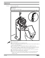
Adjustment
12 - 27
12.
05.06
Control cams to the bobbin opener and cutter
( adjustment with adjustment gauge )
Requirements
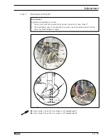
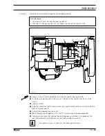
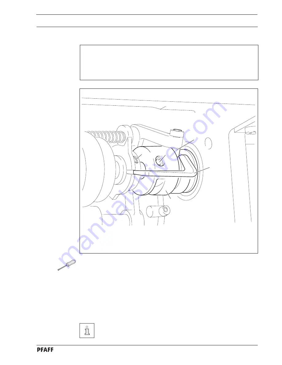
With the needle bar at BDC, both control cams must be positioned in such a way that
1. adjustment gauge
5
can be slid into the grooves of both control cams,
2. both cams are on the rests of adjustment gauge
5
and
3. the bent section of adjustment gauge
5
is touching roller
3.
1
2
4
5
3
Fig. 12 - 23
●
Loosen screws
1
and
2.
●
Bring the needle bar to BDC and activate the tripping lever by hand ( roller
3
engaged ).
●
Adjust the control cams in accordance with the
requirement
and insert adjustment
gauge
5
.
●
Turn control curve
4
in accordance with the
requirement.
●
Taking care to ensure that control cam
4
is touching the bearing collar, tighten the
accessible screws
1
and
2
.
●
Remove adjustment gauge
5
and tighten the remaining screws
1
and
2
.
For adjustment without the gauge see chapter
12.05.07 Radial position of the
control cam in relation to the bobbin opener
and
chapter 12.05.08 Control
cam in relation to scissor.

