38
20
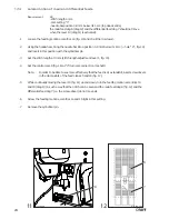
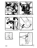
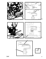
Presser foot settings
20.1
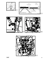
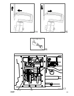
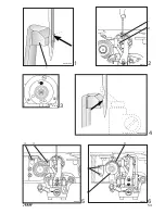
Clearance between presser foot and needle plate
Requirement:
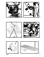
With the hand lever 1 (fig. 1) raised the clearance between the presser foot 2
and the needle plate 3 (fig. 3) should be 5 mm.
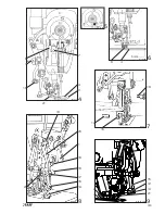
.1
Bring the top feed 4 (fig. 3) to its highest position (handwheel).
.2
Lift the presser shaft 5 and slide the 5 mm thick adjustment gauge 6 (fig. 3) from the back,
under the
presser foot joint.
.3
Loosen screw 7 and bring the presser shaft lifter 8 to its bottom resting position.
Note:
Take care that the hand lever 1 is still in its upwards position!
.4
Tighten screw 4.
.5
Check that:
- the edge of the presser foot is parallel to the needle plate cutout
- the needle enters the presser foot needle hole exactly in the middle.
If necessary, align the presser foot as described in chapter 20.3.
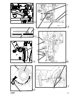
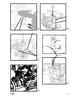
20.2
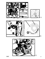
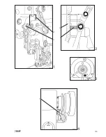
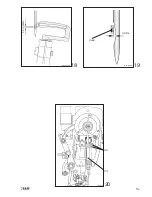
Presser foot stroke with the automatic presser foot lifter
Requirement:
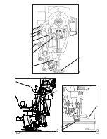
With the plunger 9 (fig. 1) retracted, the clearance between the presser foot 2
and the needle plate should be 7 mm (fig. 3)
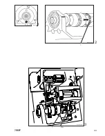
.1
Loosen nut 10.
.2
Twist the plunger 9 into or out of the presser shaft lifter 11 (fig. 1) until the presser foot 2 is
approx. 7 mm above the needle plate 3 when the plunger 9 is retracted.
.3
Tighten nut 10.
Bi21-01
Summary of Contents for 3811-11/43
Page 9: ...9 1 1 2 3 1 Bi34 01 CDR 2 4 3 Bi03 03 CDR ...
Page 11: ...11 4 1 Min Oil level Max Oil level 1 2 Bi08 01 Bi18 05 Bi08 04 CDR Bi02 01 3 ...
Page 13: ...13 3 2 1 4 1 Bi11 01 CDR 2 3 Bi11 02 Bi11 04 Bi11 03 ca 7cm ...
Page 15: ...15 2 Bi12 02 CDR Bi12 03 CDR 3 6 1 2 4 5 1 3 Bi12 01 CDR ...
Page 17: ...17 4 Bi14 04 5 Bi14 05 Schematic diagram 7 6 Bi14 03 3 6 4 5 7 4 7 5 0 8mm Bi14 02 CDR 2 3 ...
Page 19: ...19 Bi01 01 1 1 2 Bi16 02 CDR 11mm Bi14 03 3 1 2 ...
Page 21: ...21 5 Bi17 03 CDR 3 4 Bi17 04 CDR 2 Bi17 03 3 4 4 Bi17 05x CDR 5 ...
Page 27: ...27 18 Bi17 18 CDR 19 2x 18 17 20 2x 20 Bi17 20 CDR 17 19 2x 18 20 2x 19 Bi01 01 1 ...
Page 31: ...31 Bi18 16 Bi18 05 4 1 4 Bi01 01 16 5mm Bi18 17 CDR 3 2 2 1 3 1 2 ...
Page 39: ...39 Bi14 03 1 Bi14 03B 7mm 2 3 4 2 3 1 9 8 7 11 5 Bi20 03 CDR 10 10 5 1 6 ...
Page 43: ...43 1 Bi01 01 1 3 Bi17 20 CDR Bi20 02 CDR 1 2 1 2 2x ...
Page 49: ...49 Bi21 15 CDR 14 15 Bi21 16 CDR 16 Part No 08 880 137 00 Bi21 17 17 Bi17 04 CDR 20 21 2x ...
Page 51: ...51 Bi21 18 CDR 18 1 0 1 2mm Bi14 03 22 23 20 19 Bi21 19 CDR 0 1mm Hook ...
Page 53: ...53 Bi22 21 CDR Bi21 11 2 1 2 1 1 Bi01 01 3 3 Bi22 04 CDR 4 Bi22 05 5 6 Bi22 06 3 4 6 7 5 ...
Page 55: ...55 Bi24 01 CDR 1 2 Bi22 06 2 1 1 4 3 5 2 Bi24 04 CDR 0 3 0 5mm 3 4 1 ...
Page 57: ...57 0 3mm Bi25 01 1 1 2 Bi26 01 Bi26 02 2 3 3 1 3 4 Bi27 01 4 5 ...
Page 59: ...59 Bi29 04 CDR 5 4 1 3 4 Bi29 03 CDR 8mm 3 Bi28 01 1 1 2 5 4 3 6 Bi01 01 1 2 29mm ...
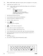
Page 63: ...63 7 6 5 Tastenfeld von 11 43 11 45 13 45 Bi31 02 CDR Bi19 04 CDR ...
Page 69: ...69 1 Bi33 01 CDR 3 1 2 4 Tastenfeld 11 43 11 45 13 45 2 Bi02 03 CDR ...


