Adjustment
30
1
.06.02
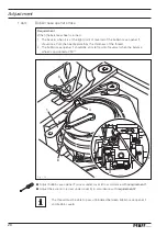
Position and height of the thread catcher
Requirement
When the needle bar is positioned at b.d.c. (balance wheel position
180
°) the edges of
thread catcher
3
and knife
5
should be fl ush (see arrow).
●
Press roller lever
1
against control cam
2
.
●
Adjust thread catcher
3
(screw
4
) in accordance with the
requirement
The height of thread catcher
3
is pre-set by the manufacturer and, if necessary,
it can be adjusted with washers under thread catcher
3
on the base of the hook
bearing.
Fig. 1 - 23
2
4
1
127-096
3
5
Summary of Contents for Powerline 2545
Page 47: ...47 Circuit diagrams Version 27 07 07 91 191 523 95 Part 1 ...
Page 48: ...48 91 191 523 95 Part 2 Version 27 07 07 Circuit diagrams ...
Page 51: ...51 Circuit diagrams Version 10 08 10 91 191 519 95 Part 1 ...
Page 52: ...52 91 191 519 95 Part 2 Version 20 04 12 Circuit diagrams ...
Page 53: ...53 Circuit diagrams Version 20 04 12 91 191 519 95 Part 3 ...
Page 54: ...54 91 191 519 95 Part 4 Version 20 04 12 Circuit diagrams ...


