Adjusting
39
Fig. 1 - 31
1
.07.07
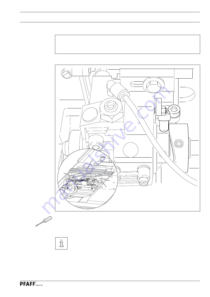
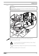
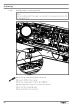
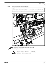
Thread catcher height
Rule
When positioning the thread catcher
2
under the setting gauge
1
, the thread catcher
2
should directly touch the setting gauge
1
without turning it.
●
Place the setting gauge
1
(Order No.
61
-
111
689
-
07
) in the needle plate recess, so that it
stands above the thread catcher
2
(see magnifi cation).
The height setting is factory preset.
Any possible correction required can be carried out by placing a
0
.
2
mm
thick
spacing washer underneath (Order No.
12-360 061-05
) between part
3
and
part
4
.
1
2
4
3
Summary of Contents for Powerline 2545
Page 47: ...47 Circuit diagrams Version 27 07 07 91 191 523 95 Part 1 ...
Page 48: ...48 91 191 523 95 Part 2 Version 27 07 07 Circuit diagrams ...
Page 51: ...51 Circuit diagrams Version 10 08 10 91 191 519 95 Part 1 ...
Page 52: ...52 91 191 519 95 Part 2 Version 20 04 12 Circuit diagrams ...
Page 53: ...53 Circuit diagrams Version 20 04 12 91 191 519 95 Part 3 ...
Page 54: ...54 91 191 519 95 Part 4 Version 20 04 12 Circuit diagrams ...


