


Adjustment
113
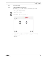
4
.10
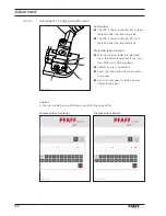
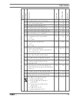
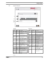
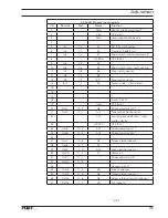
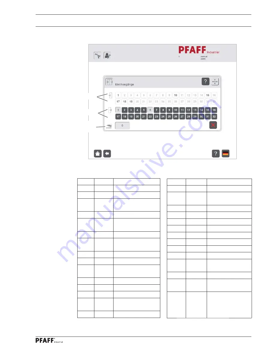
Inputs / Outputs
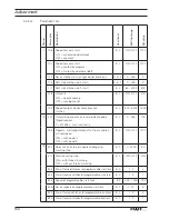
Key
Input
Function
1
E1
Ref. SM stitch setter
2
E2
E-winder
3
E7
Knee switch*
(stroke adjustment)
5
E9
6
E4
Knee switch
(man. seam section)
7
E6
Stop (safety device)
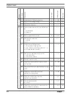
8
E8
Bobin cover in
reading position
9
E11
Stop motion device
10
E3
Slide control
16
LS
Photocell straight
edge
17
E51
Bobbin lower thread
18
E52
Bobbin top thread
19
E53
Error straight edge
25 - 31
Control panel on
machine
32
Hotkey
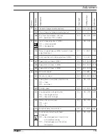
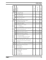
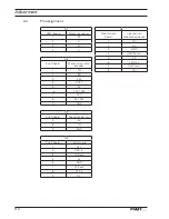
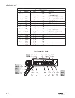
Key
Output
Function
1
A6
Stroke adjustment 0 *
2
A11
Stop motion device
reset
5
A12
Stroke adjustment 1*
6
A13
Stroke adjustment 2*
7
A3
Thread clamp
9
A15
Foot cleaning
10
A1
Motor run
11
A14
Stroke adjustment 3*
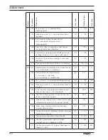
13
A5
E-winder
14
A4
Clamp foot
15
A8
Thread tension to be
released
16
A9
Cutting
17
LED docu-seam
Straight edge
25 - 40
LED on control panel
of machine
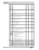
Inputs
Outputs
Input
Output
Treadle
position
* 3745
Summary of Contents for POWERLINE 3741
Page 1: ...296 12 19 008 002 Betriebsanleitung engl 06 12 DOKU SEAM SYSTEM 3741 3745 ...
Page 7: ...Register 01 ...
Page 8: ......
Page 14: ......
Page 15: ...Register 02 ...
Page 16: ......
Page 43: ...Register 03 ...
Page 44: ......
Page 81: ...Register 04 ...
Page 82: ......
Page 126: ......
Page 127: ...Register 05 ...
Page 128: ......
Page 129: ...Kalibrieranleitung engl 06 12 CALIBRATION INSTRUCTIONS 3741 3745 ...
Page 139: ...Register 06 ...
Page 140: ......
Page 147: ...135 91 191 528 95 Part 1 Version 12 01 12 Circut diagrams ...
Page 148: ...136 Circut diagrams Version 12 01 12 91 191 528 95 Part 2 ...
Page 149: ...137 91 191 528 95 Part 3 Version 12 01 12 Circut diagrams ...
Page 150: ...138 Circut diagrams Version 12 01 12 91 191 528 95 Part 4 ...
Page 151: ...139 91 191 528 95 Part 5 Version 12 01 12 Circut diagrams ...
Page 152: ...140 Circut diagrams Version 12 01 12 91 191 528 95 Part 6 ...
Page 153: ...141 91 191 528 95 Part 7 Version 12 01 12 Circut diagrams ...
Page 154: ...142 Circut diagrams Version 05 01 12 91 191 536 95 ...
Page 155: ...143 91 191 536 95 Version 12 01 12 Circut diagrams ...


